Engine Front Cover: Installation
WARNING: This page is about a different variant/trim than selected.
- 1.
Clean the engine front cover using a 3M™ Roloc ® Bristle Disk (2 in white, part number 07528) in a suitable tool turning at the recommended speed of 15, 000 RPM.- Thoroughly wash the engine front cover to remove any foreign material, including any abrasive particles created during the cleaning process.
NOTE:
Only use a 3M™ Roloc ® Bristle Disk (2 in white, part number 07528), to clean the engine front cover. Do not use metal scrapers, wire brushes or any other power abrasive disk to clean the engine front cover.
- 2.
Clean the sealing surfaces of the cylinder heads, the cylinder block and the oil pan in the following sequence.- 1.
Remove any large deposits of silicone or gasket material with a plastic scraper.
- 2.
Apply silicone gasket remover, following package directions and allow to set for several minutes.
- 3.
Remove the silicone gasket remover with a plastic scraper. A second application of silicone gasket remover may be required if residual traces of silicone or gasket material remain.
- 4.
Apply metal surface prep, following package directions, to remove any remaining traces of oil or coolant and to prepare the surfaces to bond. Do not attempt to make the metal shiny. Some staining of the metal surfaces is normal.
- 5.
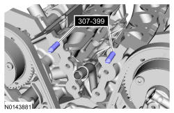
Make sure the 2 locating dowel pins are seated correctly in the cylinder block.
- 1.
NOTE:
Observe all warnings or cautions and follow all application directions contained on the packaging of the silicone gasket remover and the metal surface prep.
NOTE:
Do not use wire brushes, power abrasive discs or 3M™ Roloc ® Bristle Disk (2-in white, part number 07528) to clean the sealing surfaces of the engine block, cylinder heads, and oil pan. These tools cause contamination that can cause premature engine failure. Remove all traces of sealant, including any sealant from the inner surface of the cylinder block and cylinder head.
NOTE:
Place clean, lint free shop towels over exposed engine cavities. Carefully remove the towels so foreign material is not dropped into the engine. Any foreign material (including any material created while cleaning gasket surfaces) that enters the oil passages or the oil pan, may cause engine failure.
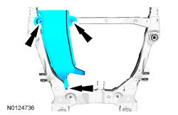
- 4.
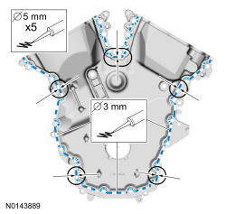
Apply a 3.0 mm (0.11 in) bead of silicone to the engine front cover sealing surfaces including the 3 engine mount bracket bosses.- Apply a 5.5 mm (0.21 in) bead of silicone to the oil pan-to-cylinder block joint and the cylinder head-to-cylinder block joint areas of the engine front cover in 5 places as indicated.
NOTE:
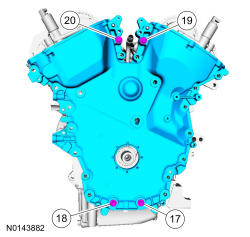
The engine front cover and bolts 17, 18, 19 and 20 must be installed within 4 minutes of the initial sealant application. The remainder of the engine front cover bolts and the engine mount bracket bolts must be installed and tightened within 35 minutes of the initial sealant application. If the time limits are exceeded, the sealant must be removed, the sealing area cleaned and sealant reapplied. To clean the sealing area, use silicone gasket remover and metal surface prep. Failure to follow these instructions can cause future oil leakage.
NOTE:
Failure to use Motorcraft ® High Performance Engine RTV Silicone may cause the engine oil to foam excessively and result in serious engine damage.
- 5.
Install the engine front cover and bolts 17, 18, 19 and 20.- Tighten in sequence to 3 Nm (27 lb-in).
NOTE:
Make sure the 2 locating dowel pins are seated correctly in the cylinder block.
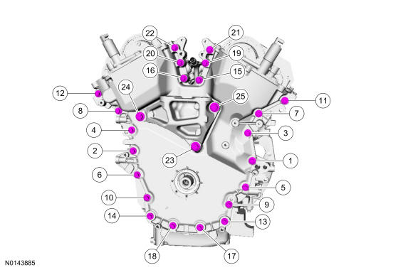
- 10.
Install the remaining engine front cover bolts. Tighten all of the engine front cover bolts and engine mount bracket bolts in the sequence shown in 2 stages:- Stage 1: Tighten bolts 1 thru 22 to 10 Nm (89 lb-in) and bolts 23, 24 and 25 to 15 Nm (133 lb-in).
- Stage 2: Tighten bolts 1 thru 22 to 24 Nm (18 lb-ft) and bolts 23, 24 and 25 to 75 Nm (55 lb-ft).
NOTE:
Do not expose the Motorcraft ® High Performance Engine RTV Silicone to engine oil for at least 90 minutes after installing the engine front cover. Failure to follow this instruction may cause oil leakage.
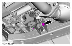
- 11.
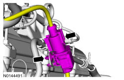
Install the HO2S connector bracket and stud bolt.- Tighten to 10 Nm (89 lb-in).
- Attach the HO2S electrical connector.
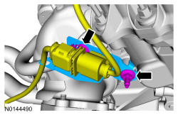
- 12.
Install the engine mount. Refer to Engine Mount .
- 13.
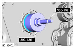
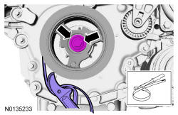
Special Tool(s): Installer, Front Crankshaft Seal 303-1251 and Installer, Crankshaft Vibration Damper 303-102 (T74P-6316-B). Install a new crankshaft front seal.
NOTE:
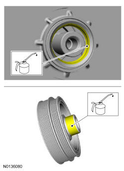
Apply clean engine oil to the crankshaft front seal bore in the engine front cover.
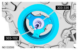
- 15.
Special Tool(s): Installer, Front Cover Oil Seal 303-335 and Installer, Crankshaft Vibration Damper 303-102 (T74P-6316-B). Install the crankshaft pulley.
- 16.
General Equipment: Strap Wrench. Install the crankshaft pulley washer and new bolt and tighten in 4 stages.- Stage 1: Tighten to 120 Nm (89 lb-ft).
- Stage 2: Loosen one full turn.
- Stage 3: Tighten to 50 Nm (37 lb-ft).
- Stage 4: Tighten an additional 90 degrees.
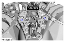
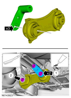
- 17.
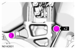
Position the rear roll restrictor bracket with the keyed tabs aligned to the rear roll restrictor and install the 2 bolts.- 1.
Tighten the 2 bolts to 103 Nm (76 lb-ft).
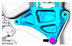
- 2.
Tighten the bolt to 103 Nm (76 lb-ft).
- 1.
NOTE:
The bracket has 3 keyed tabs to orient the roll restrictor.
- 19.
Install the accessory drive belt tensioner and belt. REFER to Accessory Drive .
- 20.
Install the RH inner fender splash shield. REFER to Front End Body Panels .
- 22.
Install the RH and LH valve covers. Refer to Valve Cover - RH and Valve Cover - LH .