Intake Manifold: Removal
WARNING: This page is about a different variant/trim than selected.
NOTE:
During engine repair procedures, cleanliness is extremely important. Any foreign material, including any material created while cleaning gasket surfaces that enters the oil passages, coolant passages or the oil pan, may cause engine failure.
NOTE:
Whenever turbocharger air intake system components are removed, always cover open ports to protect from debris. It is important that no foreign material enter the system. The turbocharger compressor vanes are susceptible to damage from even small particles. All components should be inspected and cleaned, if necessary, prior to installation or reassembly.
- 1.
Drain the cooling system. REFER to Engine Cooling .
- 2.
Remove the Air Cleaner (ACL) outlet pipe. REFER to Intake Air Distribution and Filtering .
- 3.
Loosen the clamp and position the CAC tube aside.
NOTE:
Index-mark the Charge Air Cooler (CAC) tube for installation.
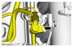
- 4.
Disconnect the LH turbocharger bypass valve electrical connector and turbocharger bypass valve hose.
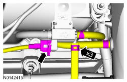
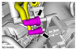
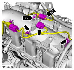
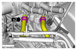
- 5.
Remove the turbocharger wastegate regulating valve hoses from the RH CAC tube and turbocharger wastegate regulating valve.- Disconnect the turbocharger wastegate regulating valve electrical connector.
NOTE:
Index-mark the hoses for installation.
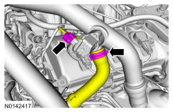
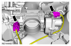
- 6.
Disconnect the RH turbocharger bypass valve electrical connector and turbocharger bypass valve hose.
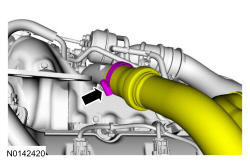
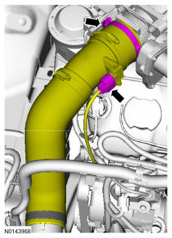
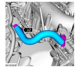
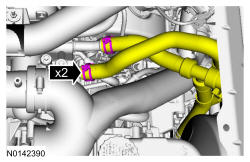
- 7.
Loosen the clamp and remove the RH CAC tube from the RH turbocharger.
NOTE:
Index-mark the CAC tube position for reference during installation.
- 8.
Remove the RH CAC tube nut from the intake manifold and remove the RH CAC tube and turbocharger intake tube as an assembly.
NOTE:
The compression limiter bushing may fall out of the mounting bracket grommet on the Charge Air Cooler (CAC) tube during service. Make sure the bushing is in place when reinstalling the tube or damage to the tube may occur.
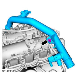
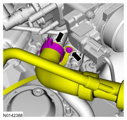
- 9.
Disconnect the TCBP /CAC electrical connector and loosen the clamp. Position the CAC outlet pipe aside.
NOTE:
Index-mark the Charge Air Cooler (CAC) tube for installation.
- 11.
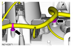
Disconnect the EVAP tube and brake booster vacuum hose quick connect couplings from the intake manifold. REFER to Fuel System General Information .
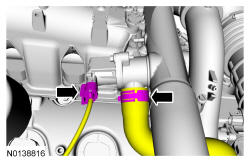
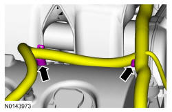
- 13.
Disconnect the 2 quick connect couplings and remove the PCV tube. REFER to Fuel System General Information .
- 14.
Disconnect the Manifold Absolute Pressure(MAP) /Intake Air Temperature 2 (IAT2) sensor electrical connector.- Detach and disconnect the 2 fuel injector wiring harness electrical connectors and the 2 wiring harness retainers.
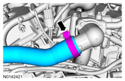
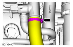
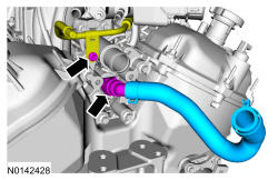
- 20.
Remove the bolt and ground wire from the engine front cover.- Disconnect the upper radiator hose from the intake manifold coolant tube.
- 21.
Remove the coolant tube and remove the fuel tube-to-engine front cover bracket bolt and position the fuel tube aside.
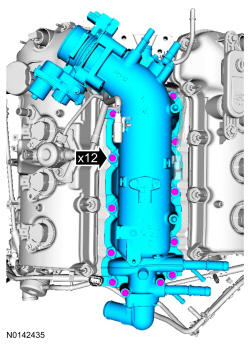
- 22.
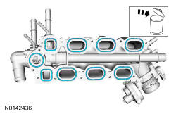
Remove the 12 bolts and the intake manifold.- Clean and inspect all sealing surfaces.
NOTE:
Note the routing of the 2 fuel rail wiring harnesses for installation.
NOTE:
If the engine is repaired or replaced because of upper engine failure, typically including valve or piston damage, check the intake manifold for metal debris. If metal debris is found, install a new intake manifold. Failure to follow these instructions can result in engine damage.