Timing Drive Components: Installation
WARNING: This page is about a different variant/trim than selected.
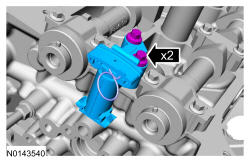
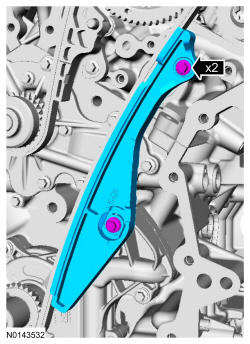
- 2.
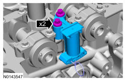
Install the RH secondary timing chain tensioner and the 2 bolts.- Tighten to 10 Nm (89 lb-in).
NOTE:
It is necessary to tilt the Camshaft Holding Tool toward the rear of the engine to access the rearmost secondary timing chain tensioner bolt.
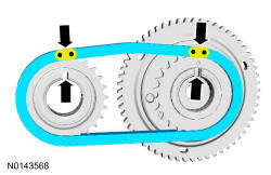
- 3.
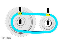
Assemble the RH Variable Camshaft Timing (VCT) assembly, the RH exhaust camshaft sprocket and the RH secondary timing chain.- Align the colored links with the timing marks.
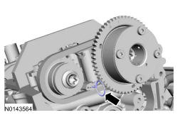
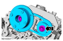
- 4.
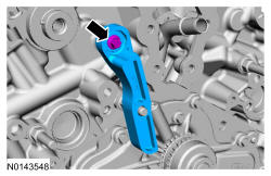
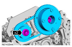
Position the RH secondary timing assembly onto the camshafts and install the new VCT bolt and the exhaust camshaft bolt and the original washer. Tighten in 4 stages.- Stage 1: Tighten to 40 Nm (30 lb-ft).
- Stage 2: Loosen one full turn.
- Stage 3: Tighten to 10 Nm (89 lb-in).
- Stage 4: Tighten 90 degrees.
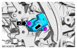
- 6.
Install the LH secondary timing chain tensioner and the 2 bolts.- Tighten to 10 Nm (89 lb-in).
NOTE:
It is necessary to tilt the Camshaft Holding Tool toward the rear of the engine to access the rearmost secondary timing chain tensioner bolt.
- 7.
Assemble the LH VCT assembly, the LH exhaust camshaft sprocket and the LH secondary timing chain.- Align the colored links with the timing marks.
- 8.
Position the LH secondary timing assembly onto the camshafts and install the new VCT bolt and the exhaust camshaft bolt and the original washer. Tighten in 4 stages.- Stage 1: Tighten to 40 Nm (30 lb-ft).
- Stage 2: Loosen one full turn.
- Stage 3: Tighten to 10 Nm (89 lb-in).
- Stage 4: Tighten 90 degrees.
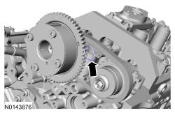
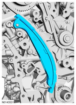
- 12.
Install the primary timing chain with the colored links aligned with the timing marks on the VCT assemblies and the crankshaft sprocket.
NOTE:
The crankshaft sprocket timing mark should be between the 2 colored links.
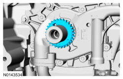
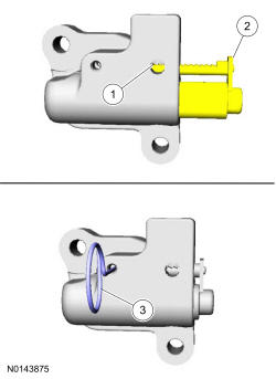
- 15.
Reset the primary timing chain tensioner.- 1.
Release the ratchet detent.
- 2.
Using a soft-jawed vise, compress the ratchet plunger.
- 3.
Align the hole in the ratchet plunger with the hole in the tensioner housing and install a suitable lockpin.
- 1.
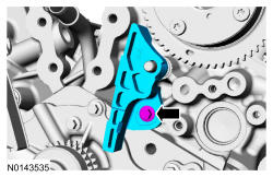
- 16.
Install the primary tensioner and the 2 bolts.- Tighten to 10 Nm (89 lb-in).
- Remove the Lock Pin.
NOTE:
It may be necessary to rotate the crankshaft slightly to remove slack from the timing chain and install the tensioner.
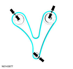
- 17.
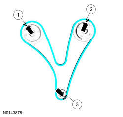
As a post-check, verify correct alignment of all timing marks.- There are 48 links between the RH intake VCT assembly colored link (1) and the LH intake VCT assembly colored link (2).
- There are 35 links between the LH intake VCT assembly colored link (2) and the 2 crankshaft sprocket colored links (3).
- 18.
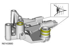
Visual check the VCT housing-to-cylinder head O-ring seals and VCT housing seals for damage and replace as necessary.
NOTE:
During removal, the O-ring seal may remain on the cylinder head. If so, remove the O-ring seal from the cylinder head, inspect the seal (replace as necessary) and install the O-ring seal on the VCT housing.
NOTE:
RH shown, LH similar.
- 19.
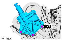
Install the LH VCT housing and the 3 bolts.- Tighten in the sequence shown to 10 Nm (89 lb-in).
NOTE:
Make sure the dowels on the Variable Camshaft Timing (VCT) housing are fully engaged in the cylinder head prior to tightening the bolts. Failure to follow this process will result in severe engine damage.
- 20.
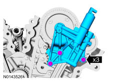
Install the RH VCT housing and the 3 bolts.- Tighten in the sequence shown to 10 Nm (89 lb-in).
NOTE:
Make sure the dowels on the Variable Camshaft Timing (VCT) housing are fully engaged in the cylinder head prior to tightening the bolts. Failure to follow this instruction will result in severe engine damage.
- 21.
Install the engine front cover. Refer to Engine Front Cover .