Valve Cover - LH: Installation
WARNING: This page is about a different variant/trim than selected.
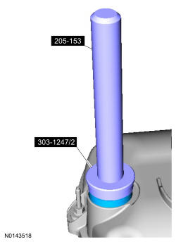
- 1.
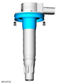
Special Tool(s): Installer, VCT Spark Plug Tube Seal 303-1247/2 and Handle 205-153 (T80T-4000-W). Install new VCT solenoid and/or spark plug tube seals.
NOTE:
Installation of new seals is only required if damaged seals were removed during disassembly of the engine.
NOTE:
VCT solenoid seal installation shown, spark plug tube seal removal similar.
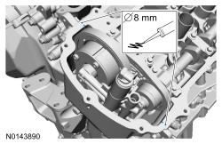
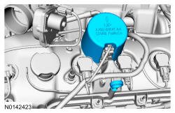
- 3.
Apply a continuous bead of the specified diameter from the specified cartridge.
NOTE:
If the valve cover is not installed and the fasteners tightened within 4 minutes, the sealant must be removed and the sealing area cleaned. To clean the sealing area, use silicone gasket remover and metal surface prep. Failure to follow these instructions can cause future oil leakage.
NOTE:
Failure to use Motorcraft ® High Performance Engine RTV Silicone may cause the engine oil to foam excessively and result in serious engine damage.
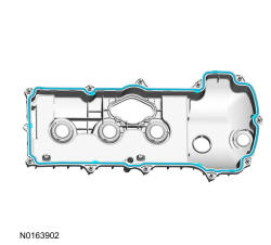
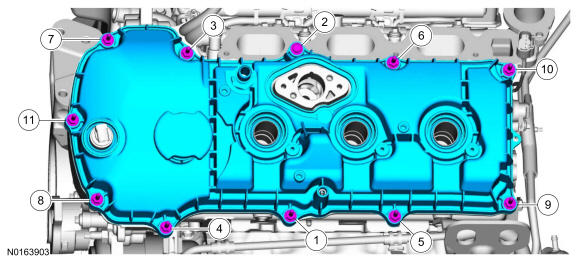
- 4.
Install the LH valve cover. Tighten the 10 stud bolts and the bolt.- Tighten in the sequence shown to 10 Nm (89 lb-in).
- 5.
Inspect the 3 ignition coil-on-plug seals for rips, nicks or tears. Remove and discard any damaged ignition coil-on-plug seals.- Slide the new ignition coil-on-plug seal onto the ignition coil-on-plug until it is fully seated at the top of the coil-on-plug.
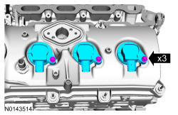
- 6.
Install the 3 LH ignition coil-on-plugs and the 3 bolts.- Tighten to 7 Nm (62 lb-in).
NOTE:
Apply a small amount of dielectric grease to the inside of the ignition coil-on-plug boots before attaching to the spark plugs.
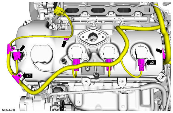
- 7.
Connect the LH VCT solenoid and the 3 LH ignition coil-on-plug electrical connectors.- Attach all of the wiring harness retainers to the LH valve cover and stud bolts.
- 8.
Install the fuel injection pump. FUEL CHARGING AND CONTROLS - 3.5L GTDI .
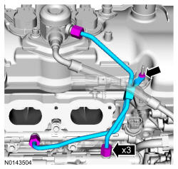
- 9.
Install the high-pressure fuel tube and tighten the 3 flare nuts in the following 3 stages.- Stage 1: Tighten to 32 Nm (24 lb-ft).
- Stage 2: Wait 10 minutes to minimize pre-stress.
- Stage 3: Tighten to 32 Nm (24 lb-ft).
- Install the new high-pressure fuel tube bracket nut.
- Tighten the nut to 8 Nm (71 lb-in).
NOTE:
Apply clean engine oil to the threads of the 3 high-pressure fuel tube flare nuts.
- 10.
Install the intake manifold. Refer to Intake Manifold .
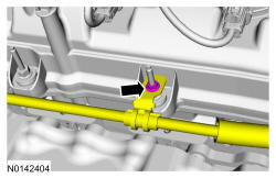
- 11.
Install the oil supply tube bracket on the LH valve cover stud bolt and install the nut.- Tighten to 8 Nm (71 lb-in).
- 12.
Install the noise insulator shield for the fuel injection pump and install the oil level indicator.
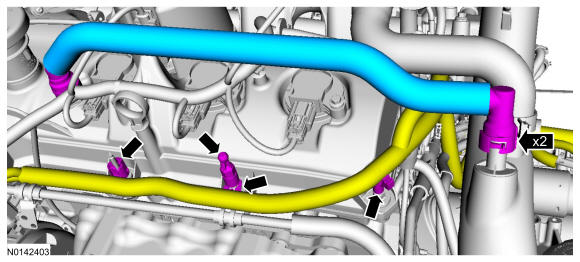
- 13.
Install the crankcase vent tube and connect the 2 quick connect couplings. REFER to Fuel System General Information .- Attach the 3 wiring harness retainers and install the engine cover mounting stud.
- Tighten to 6 Nm (53 lb-in).
- Attach the 3 wiring harness retainers and install the engine cover mounting stud.
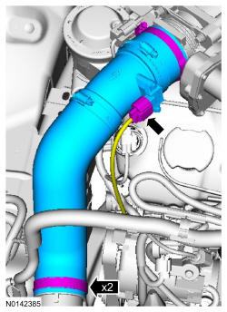
- 14.
Install the CAC outlet pipe and tighten the 2 clamps.- Tighten to 5 Nm (44 lb-in).
- Connect the TCBP /CAC electrical connector.
NOTE:
Align the index marks for the CAC outlet pipe.