Valve Cover - RH: Removal
WARNING: This page is about a different variant/trim than selected.
NOTE:
During engine repair procedures, cleanliness is extremely important. Any foreign material, including any material created while cleaning gasket surfaces that enters the oil passages, coolant passages or the oil pan, may cause engine failure.
NOTE:
Whenever turbocharger air intake system components are removed, always cover open ports to protect from debris. It is important that no foreign material enter the system. The turbocharger compressor vanes are susceptible to damage from even small particles. All components should be inspected and cleaned, if necessary, prior to installation or reassembly.
- 1.
Release the fuel system pressure. REFER to Fuel System General Information .
- 2.
Remove the Air Cleaner (ACL) outlet pipe. REFER to Intake Air Distribution and Filtering .
- 3.
Disconnect the LH turbocharger bypass valve electrical connector and turbocharger bypass valve hose.
- 4.
Remove the turbocharger wastegate regulating valve hoses from the RH Charge Air Cooler (CAC) tube and turbocharger wastegate regulating valve.
NOTE:
Index-mark the hoses for installation.
- 5.
Disconnect the RH turbocharger bypass valve electrical connector and turbocharger bypass valve hose.
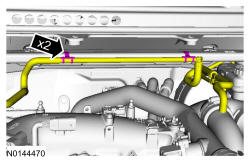
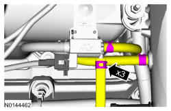
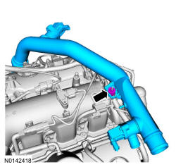
- 7.
Loosen the 2 clamps and remove the nut from the RH valve cover stud bolt and remove the RH turbocharger intake tube.
NOTE:
The compression limiter bushing may fall out of the mounting bracket grommet on the turbocharger intake tube during service. Make sure the bushing is in place when reinstalling the tube or damage to the tube may occur.
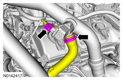
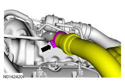
- 8.
Loosen the clamp and remove the RH CAC tube from the RH turbocharger.
NOTE:
Index-mark the CAC tube position for reference during installation.
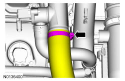
- 9.
Loosen the clamp and position the CAC tube aside.
NOTE:
Index marks the CAC tube for installation.
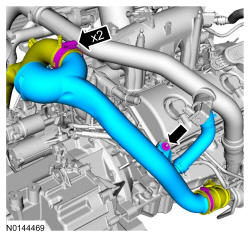
- 10.
Remove the RH CAC tube nut from the intake manifold and remove the RH CAC tube and turbocharger intake tube as an assembly.
NOTE:
The compression limiter bushing may fall out of the mounting bracket grommet on the Charge Air Cooler (CAC) tube during service. Make sure the bushing is in place when reinstalling the tube or damage to the tube may occur.
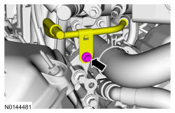
- 11.
Remove the Evaporative Emission (EVAP) canister purge valve. REFER to Evaporative Emissions .
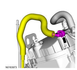
- 12.
Disconnect the fuel supply tube. REFER to Fuel System General Information .
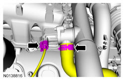
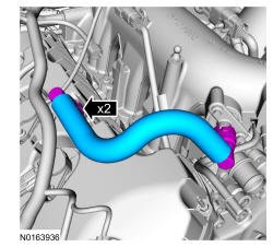
- 14.
Disconnect the 2 quick connect couplings and remove the PCV tube. REFER to Fuel System General Information .
- 15.
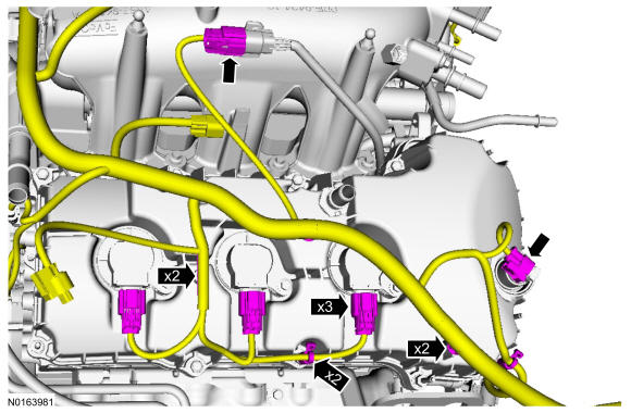
Disconnect the RH Variable Camshaft Timing (VCT) solenoid, RH fuel rail injector harness and the 3 RH ignition coil-on-plugs electrical connectors.- Detach all of the wiring harness retainers from the RH valve cover and stud bolts.
- 16.
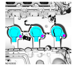
Remove the 3 bolts and the 3 RH ignition coils-on-plugs.
NOTE:
When removing the ignition coil-on-plugs, a slight twisting motion will break the seal and ease removal.
- 17.
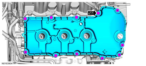
Loosen the 5 bolts and the 6 stud bolts. Remove the RH valve cover.
NOTE:
When removing the valve cover do not apply excessive force to the VCT oil control solenoid. If the VCT solenoid seal sticks to the VCT oil control solenoid carefully wiggle the valve cover until the seal breaks free. After the valve cover is removed, inspect and replace the VCT solenoid if damaged.
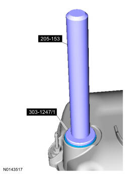
- 19.
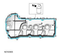
Inspect the VCT solenoid seals and the spark plug tube seals. Install new seals if damaged.- Special Tool(s): Remover, VCT Spark Plug Tube Seal 303-1247/1 and Handle 205-153 (T80T-4000-W).
NOTE:
VCT solenoid seal removal shown, spark plug tube seal removal similar.