Valve Cover - RH: Installation
WARNING: This page is about a different variant/trim than selected.
- 1.
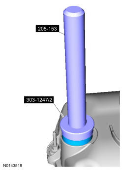
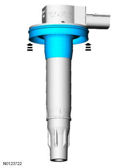
Special Tool(s): Installer, VCT Spark Plug Tube Seal 303-1247/2 and Handle 205-153 (T80T-4000-W). Install new VCT solenoid and/or spark plug tube seals.
NOTE:
Installation of new seals is only required if damaged seals were removed during disassembly of the engine.
NOTE:
VCT solenoid seal installation shown, spark plug tube seal removal similar.
- 3.
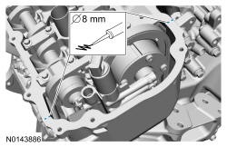
Apply an 8 mm (0.31 in) bead of silicone to the engine front cover-to-RH cylinder head joints.
NOTE:
If the valve cover is not installed and the fasteners tightened within 4 minutes, the sealant must be removed and the sealing area cleaned. To clean the sealing area, use silicone gasket remover and metal surface prep. Failure to follow these instructions can cause future oil leakage.
NOTE:
Failure to use Motorcraft ® High Performance Engine RTV Silicone may cause the engine oil to foam excessively and result in serious engine damage.
- 4.
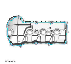
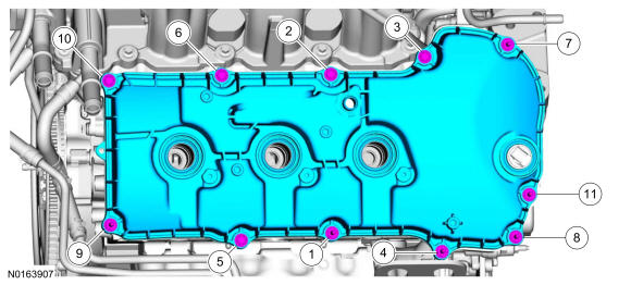
Install the RH valve cover. Tighten the 6 stud bolts and the 5 bolts.- Tighten in the sequence shown to 10 Nm (89 lb-in).
- 5.
Inspect the 6 ignition coil-on-plug seals for rips, nicks or tears. Remove and discard any damaged ignition coil-on-plug seals.- Slide the new ignition coil-on-plug seal onto the ignition coil-on-plug until it is fully seated at the top of the coil-on-plug.
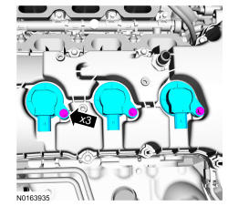
- 6.
Install the 3 RH ignition coil-on-plugs and the 3 bolts.- Tighten to 7 Nm (62 lb-in).
NOTE:
Apply a small amount of dielectric grease to the inside of the ignition coil-on-plug boots before attaching to the spark plugs.
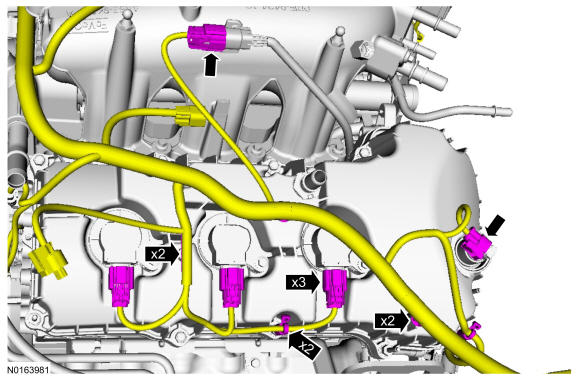
- 7.
Connect the RH VCT solenoid, RH fuel rail injector harness and the 3 RH ignition coil-on-plugs electrical connectors.- Attach all of the wiring harness retainers to the RH valve cover and stud bolts.
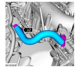
- 8.
Install the PCV tube and connect the 2 quick connect couplings. REFER to Fuel System General Information .
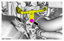
- 9.
Position the fuel tube and install the fuel tube-to-engine front cover bracket bolt.- Tighten to 10 Nm (89 lb-in).
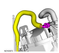
- 10.
Connect the fuel supply tube. REFER to Fuel System General Information .
- 11.
Install the EVAP canister purge valve. REFER to Evaporative Emissions .
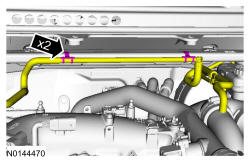
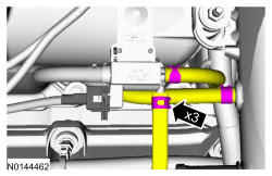
- 12.
Install the RH Charge Air Cooler (CAC) tube and turbocharger intake tube as an assembly and install the RH CAC tube nut to the intake manifold.- Tighten to 6 Nm (53 lb-in).
NOTE:
The compression limiter bushing may fall out of the mounting bracket grommet on the Charge Air Cooler (CAC) tube during service. Make sure the bushing is in place when reinstalling the tube or damage to the tube may occur.
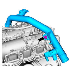
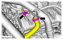
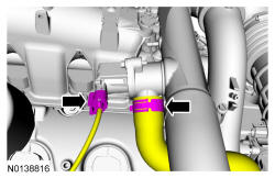
- 13.
Position the CAC tube and tighten the clamp.- Tighten to 5 Nm (44 lb-in).
NOTE:
Align the index marks for the CAC tube.
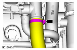
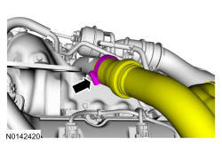
- 14.
Install the RH CAC tube to the RH turbocharger and tighten the clamp.- Tighten to 5 Nm (44 lb-in).
NOTE:
Align the index marks for the RH CAC tube.
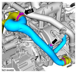
- 15.
Install the RH turbocharger intake tube and the nut.- Tighten the nut to 6 Nm (53 lb-in).
- Tighten the clamps to 5 Nm (44 lb-in).
NOTE:
The compression limiter bushing may fall out of the mounting bracket grommet on the turbocharger intake tube during service. Make sure the bushing is in place when reinstalling the tube or damage to the tube may occur.
- 17.
Install the turbocharger bypass valve hose and connect the RH turbocharger bypass valve electrical connector.
- 18.
Install the turbocharger wastegate regulating valve hoses to the RH CAC tube and turbocharger wastegate regulating valve.
- 20.
Install the ACL outlet pipe. REFER to Intake Air Distribution and Filtering .