Section 3 (Engine - 3.5L GTDI): Removal: Camshaft: Removal
WARNING: This page is about a different variant/trim than selected.
WARNING:
Before beginning any service procedure in this article, refer to Safety Warnings in SERVICE INFORMATION
.
NOTE:
During engine repair procedures, cleanliness is extremely important. Any foreign material, including any material created while cleaning gasket surfaces, that enters the oil passages, coolant passages or the oil pan may cause engine failure.
NOTE:
Whenever turbocharger air intake system components are removed, always cover open ports to protect from debris. It is important that no foreign material enter the system. The turbocharger compressor vanes are susceptible to damage from even small particles. All components should be inspected and cleaned, if necessary, prior to installation or reassembly.
All camshafts
- 1.
With the vehicle in NEUTRAL, position it on a hoist. REFER to Jacking and Lifting .
- 2.
Recover the A/C system. REFER to Climate Control DATC or REFER to Climate Control EMTC .
- 3.
Release the fuel system pressure. REFER to Fuel System General Information .
- 4.
Remove the cowl panel. REFER to Front End Body Panels .
- 5.
Remove the engine ACL and ACL outlet pipe. REFER to Intake Air Distribution and Filtering .
- 6.
Remove the battery tray. REFER to Battery, Mounting and Cables .
- 8.
Disconnect the engine wiring harness electrical connector and remove the retainer and the ground wires.
- 9.
Remove the front wheels and tires. REFER to Wheels and Tires .
- 10.
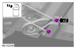
Remove the 2 RH and 2 LH lower pin-type retainers from the engine splash shields and position the shields aside.
NOTE:
RH shown, LH similar.
- 12.
Remove the accessory dive belt. REFER to Accessory Drive .
- 13.
Drain the cooling system. REFER to Engine Cooling .
- 15.
Remove the degas bottle. REFER to Engine Cooling .
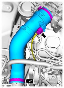
- 16.
Disconnect the Turbocharger Boost Pressure (TCBP) /Charge Air Cooler Temperature (CACT) electrical connector and loosen the 2 clamps and remove the CAC outlet pipe.
NOTE:
Index-mark the LH Charge Air Cooler(CAC) tube for installation.
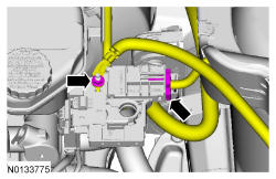
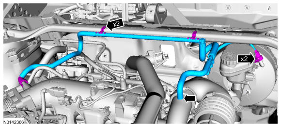
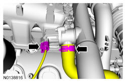
- 17.
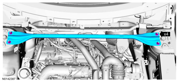
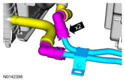
Disconnect the brake booster vacuum hose quick connect coupling from the intake manifold, brake booster and CAC. REFER to Fuel System General Information .- Detach the brake booster vacuum hose from strut tower brace.
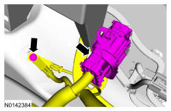
- 19.
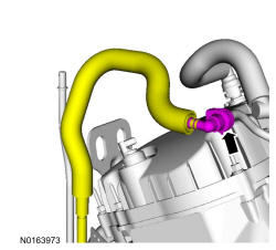
Disconnect the fuel supply tube. REFER to Fuel System General Information .
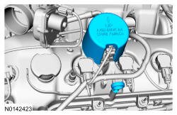
- 20.
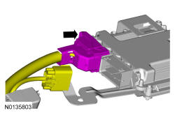
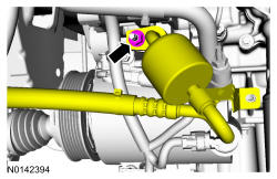
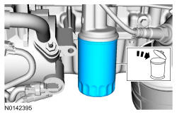
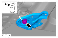
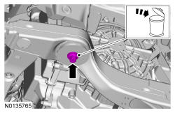
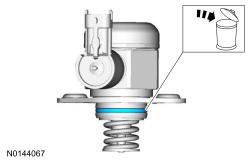
Remove the EVAP canister purge valve. REFER to Evaporative Emissions .
- 21.
Remove the bolt and ground wire from the engine front cover.- Disconnect the upper radiator hose from the intake manifold coolant tube.
- 24.
Remove the engine wiring harness retainer from the bulkhead.- 1.
Push the tab in.
- 2.
Slide the wiring harness up and out of the bulkhead.
- 1.
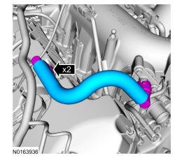
- 28.
Loosen the 2 clamps and remove the RH CAC tube.
NOTE:
Index-mark the LH Charge Air Cooler (CAC) tube for installation.
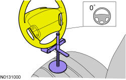
- 30.
Using a suitable holding device, hold the steering wheel in the straight-ahead position.
NOTE:
Use a steering wheel holding device (such as Hunter ® 28-75-1 or equivalent).
- 31.
Remove the bolt and disconnect the steering column shaft from the steering gear.- Discard the bolt.
NOTE:
Index-mark the steering column shaft position to the steering gear for reference during installation.
NOTE:
Do not allow the intermediate shaft to rotate while it is disconnected from the gear or damage to the clockspring may occur. If there is evidence that the intermediate shaft has rotated, the clockspring must be removed and recentered. For additional information, REFER to Supplemental Restraint System
.
- 32.
Remove the RH and LH catalytic converter. REFER to Exhaust System .
- 33.
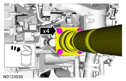
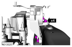
Remove and discard the 4 bolts and support the driveshaft with a length of mechanic's wire.
NOTE:
Index-mark the driveshaft for installation.
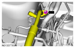
- 35.
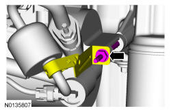
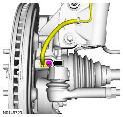
Remove the nut and disconnect the upper A/C tube from the compressor and position aside.- Discard the O-ring seal and gasket seal.
- 36.
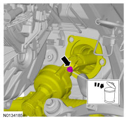
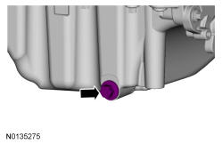
Remove the drain plug and drain the engine oil.- Install the drain plug and tighten to 27 Nm (20 lb-ft).
- 38.
Loosen the clamp and disconnect the LH CAC tube from the LH turbocharger.
NOTE:
Index-mark the LH Charge Air Cooler (CAC) tube for installation.
- 39.
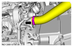
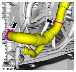
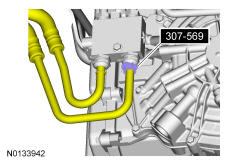
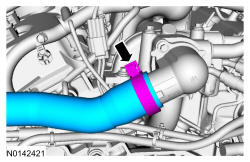
Disconnect the lower radiator hose from the radiator.- Detach the lower radiator hose retainer from the cooling fan and shroud.
- 41.
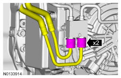
Remove the 2 secondary latches from the transmission fluid cooler tubes at the transmission fluid cooler thermal bypass valve.
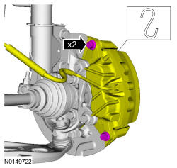
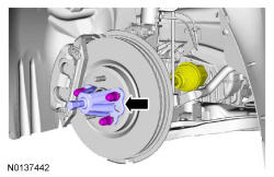
- 45.
Remove the brake caliper guide pin bolts and calipers.- Support the calipers.
NOTE:
LH shown, RH similar.
NOTE:
Do not allow the brake caliper to hang from the brake flexible hose or damage to the hose may occur.
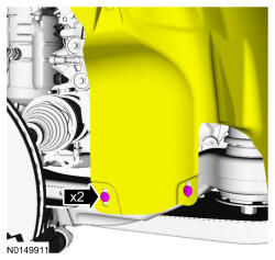
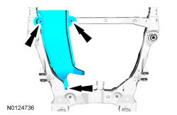
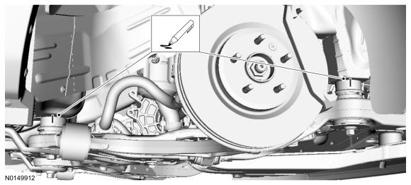
- 46.
Using a wax pencil, mark the relationship of the front and rear subframe to the underbody at the mounting locations on both side.
NOTE:
RH shown, LH similar.
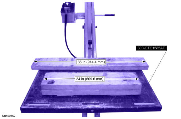
- 49.
Position a 2 x 6 board, 36 in (914.4 mm) in length and two 2 x 6 boards 24 in (609.6 mm) in length onto the powertrain lift.- Position the powertrain lift table with:
- the long board towards the rear of the subframe.
- the short boards under the engine and transmission.
- Position the powertrain lift table with:
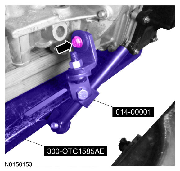
- 50.
Install the Adjustable Grip Arm from the powertrain lift table to the LH engine-to-transmission bolt hole.
- 51.
Install a ratchet strap from the front of the subframe under the powertrain lift table to the rear of the subframe, to secure the subframe to the powertrain lift table.
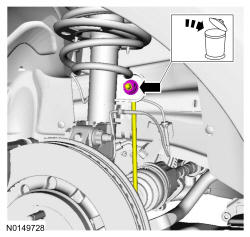
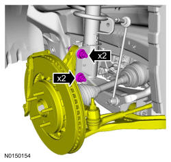
- 52.
Remove the strut-to-wheel knuckle nuts and bolts.- Remove the strut from the wheel knuckle and the halfshafts from the wheel knuckle.
NOTE:
The halfshafts are not being remove from the transmission.
NOTE:
LH shown, RH similar.
- 60.
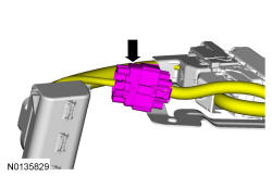
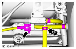
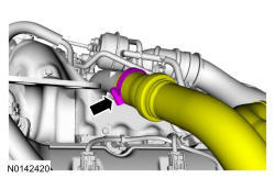
Disconnect the 2 quick connect couplings and remove the crankcase vent tube. REFER to Fuel System General Information .- Remove the engine cover mounting stud and detach the 3 wiring harness retainers.
- 63.
Remove the turbocharger wastegate regulating valve hoses from the RH CAC tube and turbocharger wastegate regulating valve.- Disconnect the turbocharger wastegate regulating valve electrical connector.
NOTE:
Index-mark the hoses for installation.
- 64.
Disconnect the RH turbocharger bypass valve electrical connector and turbocharger bypass valve hose.
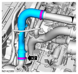
- 65.
Loosen the clamp and remove the LH turbocharger intake tube from the LH turbocharger.
NOTE:
Index-mark the CAC tube position for reference during installation.
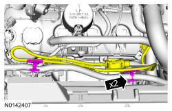
- 66.
Remove the nut from the RH valve cover stud bolt and remove the RH turbocharger intake tube.
NOTE:
The compression limiter bushing may fall out of the mounting bracket grommet on the turbocharger intake tube during service. Make sure the bushing is in place when reinstalling the tube or damage to the tube may occur.
- 67.
Loosen the clamp and remove the RH CAC tube from the RH turbocharger.
NOTE:
Index-mark the CAC tube position for reference during installation.
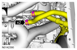
- 68.
Remove the RH CAC tube nut from the intake manifold and remove the RH CAC tube and turbocharger intake tube as an assembly.
NOTE:
The compression limiter bushing may fall out of the mounting bracket grommet on the Charge Air Cooler (CAC) tube during service. Make sure the bushing is in place when reinstalling the tube or damage to the tube may occur.
- 70.
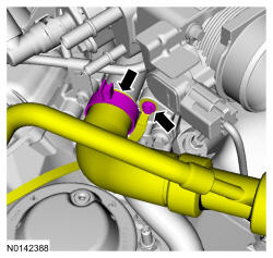
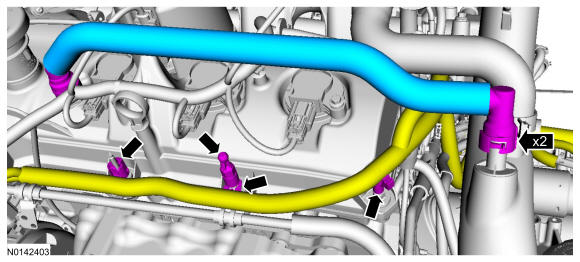
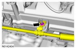
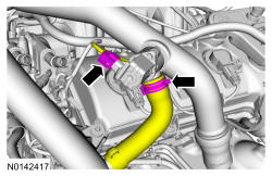
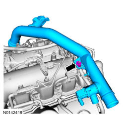
Disconnect the 2 quick connect couplings and remove the PCV tube. REFER to Fuel System General Information .
- 71.
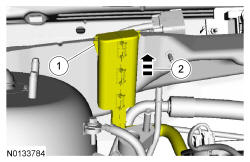
Remove the noise insulator shield for the fuel injection pump and remove the oil level indicator.
- 72.
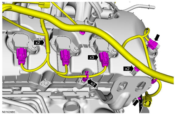
Disconnect the Throttle Position (TP) sensor, electronic TB, LH Variable Camshaft Timing (VCT) solenoid and the 3 ignition coil-on-plugs electrical connectors.- Detach all the wiring harness retainers from the LH valve cover and stud bolts.
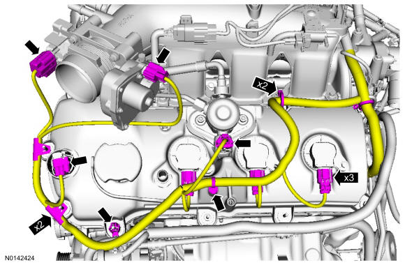
- 73.
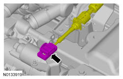
Disconnect the Engine Oil Pressure (EOP) electrical connector.- Detach the wiring harness retainer from the block.
- 74.
Disconnect the Manifold Absolute Pressure (MAP) /Intake Air Temperature 2 (IAT2) sensor electrical connector.- Detach and disconnect the 2 fuel injector wiring harness electrical connectors and the 2 wiring harness retainers.
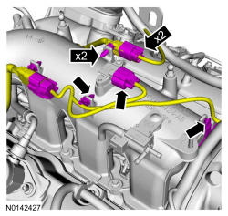
- 75.
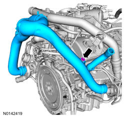
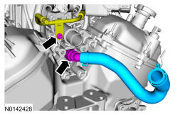
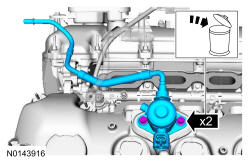
Remove the coolant tube and remove the fuel tube-to-engine front cover bracket bolt and position the fuel tube aside.
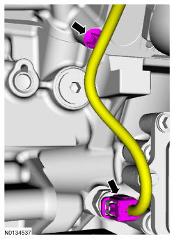
- 76.
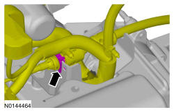
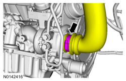
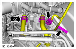
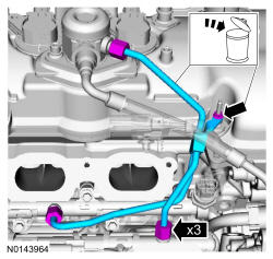
Disconnect the 2 turbocharger coolant hoses from the intake manifold and disconnect the CMP sensor electrical connector.- Detach the wiring harness retainer.
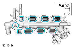
- 77.
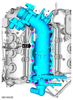
Remove the 12 bolts and the intake manifold.- Clean and inspect all sealing surfaces.
NOTE:
Note the routing of the 2 fuel rail wiring harnesses for installation.
NOTE:
If the engine is repaired or replaced because of upper engine failure, typically including valve or piston damage, check the intake manifold for metal debris. If metal debris is found, install a new intake manifold. Failure to follow these instructions can result in engine damage.
- 79.
Disconnect the RH VCT solenoid and the 3 ignition coil-on-plug electrical connectors.- Detach all the wiring harness retainers.
- 80.
Remove the nut for from the LH valve cover stud bolt and remove the high pressure fuel tube flare nuts from the fuel injection pump and fuel rail.- Discard the tube and nut.
NOTE:
To release the fuel pressure in the high pressure fuel tube, wrap the flare nut with a shop towel to absorb any residual fuel pressure during the loosening of the flare nut.
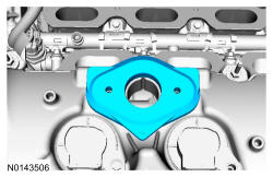
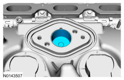
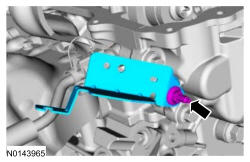
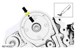
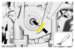
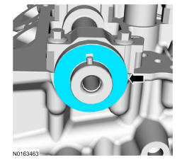
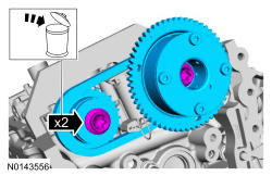
- 85.
Inspect the fuel injection pump roller tappet for flat spots or scoring, especially in the indicated areas. If any damage is found, inspect the fuel injection pump roller tappet camshaft lobe. Install new components as necessary.
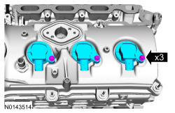
- 86.
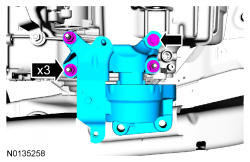
Remove the 3 bolts and the 3 LH ignition coils-on-plugs.
NOTE:
When removing the ignition coil-on-plugs, a slight twisting motion will break the seal and ease removal.
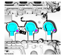
- 87.
Remove the 3 bolts and the 3 RH ignition coils-on-plugs.
NOTE:
When removing the ignition coil-on-plugs, a slight twisting motion will break the seal and ease removal.
- 88.
Loosen the bolt and the 10 stud bolts. Remove the LH valve cover.
NOTE:
When removing the valve cover do not apply excessive force to the VCT oil control solenoid. If the VCT solenoid seal sticks to the VCT oil control solenoid carefully wiggle the valve cover until the seal breaks free. After the valve cover is removed, inspect and replace the VCT solenoid if damaged.
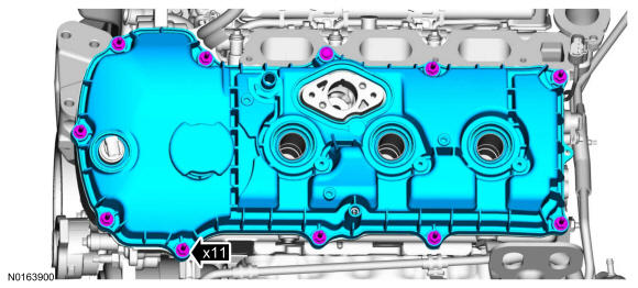
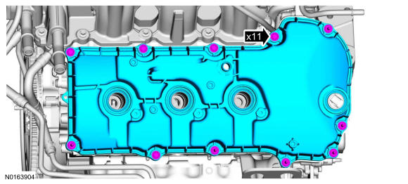
- 90.
Loosen the 5 bolts and the 6 stud bolts. Remove the RH valve cover.
NOTE:
When removing the valve cover do not apply excessive force to the VCT oil control solenoid. If the VCT solenoid seal sticks to the VCT oil control solenoid carefully wiggle the valve cover until the seal breaks free. After the valve cover is removed, inspect and replace the VCT solenoid if damaged.
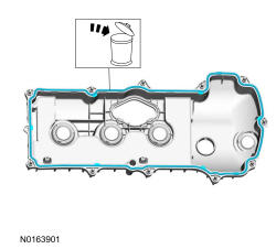
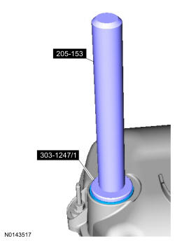
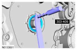
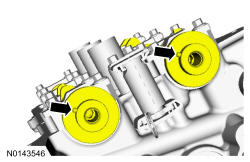
- 92.
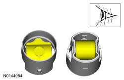
Inspect the VCT solenoid seals and the spark plug tube seals. Install new seals if damaged.- Special Tool(s): Remover, VCT Spark Plug Tube Seal 303-1247/1 and Handle 205-153 (T80T-4000-W).
NOTE:
VCT solenoid seal removal shown, spark plug tube seal removal similar.
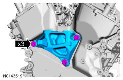
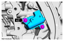
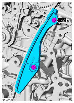
- 97.
Remove the stud bolt and the Heated Oxygen Sensor (HO2S) connector bracket from the engine front cover.

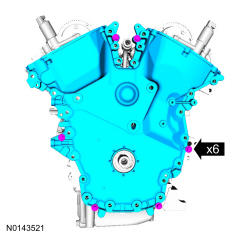
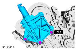
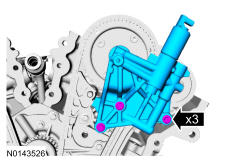
- 100.
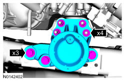
Install 6 of the engine front cover bolts (finger-tight) into the 6 threaded holes in the engine front cover.- Tighten the bolts one turn at a time in a crisscross pattern until the engine front cover-to-cylinder block seal is released.
- Remove the engine front cover.
- Tighten the bolts one turn at a time in a crisscross pattern until the engine front cover-to-cylinder block seal is released.
- 101.
Clean the engine front cover using a 3M™ Roloc ® Bristle Disk (2-in white, part number 07528) in a suitable tool turning at the recommended speed of 15, 000 RPM.- Thoroughly wash the engine front cover to remove any foreign material, including any abrasive particles created during the cleaning process.
NOTE:
Only use a 3M™ Roloc ® Bristle Disk (2-in white, part number 07528) to clean the engine front cover. Do not use metal scrapers, wire brushes or any other power abrasive disk to clean the engine front cover. These tools cause scratches and gouges that make leak paths.
- 102.
Clean the sealing surfaces of the cylinder heads, the cylinder block and the oil pan in the following sequence.- 1.
Remove any large deposits of silicone or gasket material.
- 2.
Apply silicone gasket remover and allow to set for several minutes.
- 3.
Remove the silicone gasket remover. A second application of silicone gasket remover may be required if residual traces of silicone or gasket material remain.
- 4.
Apply metal surface prep, to remove any remaining traces of oil or coolant and to prepare the surfaces to bond. Do not attempt to make the metal shiny. Some staining of the metal surfaces is normal.
- 5.
Make sure the 2 locating dowel pins are seated correctly in the cylinder block.
- 1.
NOTE:
Do not use wire brushes, power abrasive discs or 3M™ Roloc ® Bristle Disk (2-in white, part number 07528) to clean the sealing surfaces. These tools cause scratches and gouges that make leak paths. They also cause contamination that will cause premature engine failure. Remove all traces of sealant, including any sealant from the inner surface of the cylinder block and cylinder head.
NOTE:
Place clean, lint-free shop towels over exposed engine cavities. Carefully remove the towels so foreign material is not dropped into the engine. Any foreign material (including any material created while cleaning gasket surfaces) that enters the oil passages or the oil pan, may cause engine failure.
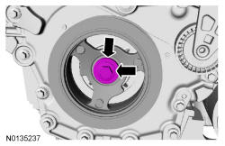
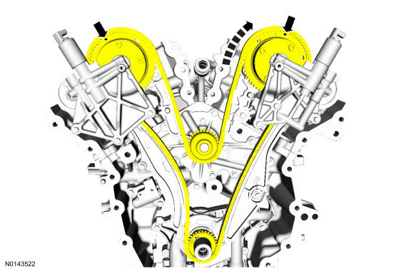
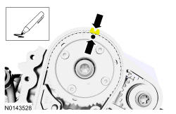
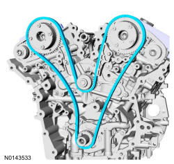
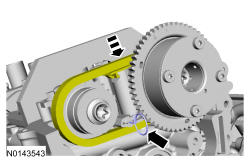
- 103.
Rotate the crankshaft clockwise and align the timing marks on the Variable Camshaft Timing (VCT) assemblies as shown.
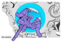
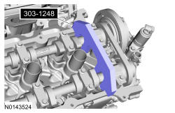
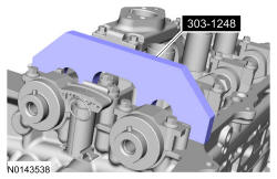
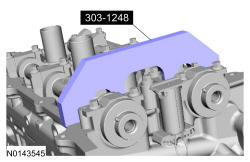
- 104.
Install the Special Tool(s): Tool, Camshaft Holding 303-1248.
NOTE:
The Camshaft Holding Tool will hold the camshafts in the Top Dead Center (TDC) position.
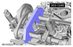
- 105.
Install the Special Tool(s): Tool, Camshaft Holding 303-1248.
NOTE:
The Camshaft Holding Tool will hold the camshafts in the TDC position.
NOTE:
The following 3 steps are for primary timing chains when the colored links are not visible.
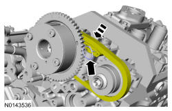
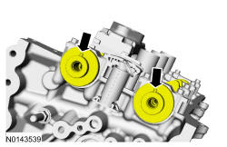
- 108.
Mark the timing chain link that aligns with the timing mark on the RH intake VCT assembly as shown.
- 109.
Mark the timing chain link that aligns with the timing mark on the LH intake VCT assembly as shown.
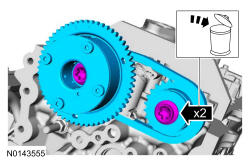
- 110.
Mark the 2 timing chain links that align with the timing mark on the crankshaft sprocket as shown.
NOTE:
The crankshaft sprocket timing mark should be between the 2 colored links.
LH camshafts
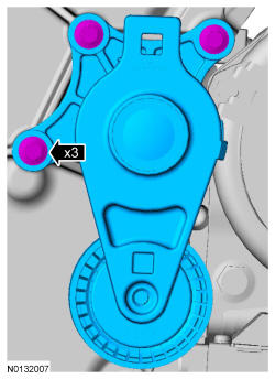
- 115.
Compress the LH secondary timing chain tensioner and install a suitable lock pin to retain the tensioner in the collapsed position.
- 116.
Remove the LH VCT assembly bolt and the LH exhaust camshaft sprocket bolt.- Remove the LH VCT assembly, secondary timing chain and the LH exhaust camshaft sprocket as an assembly.
- Discard the bolts.
NOTE:
The VCT bolt and the exhaust camshaft bolt must be discarded and new ones installed. However, the exhaust camshaft washer is reusable.
- 118.
Remove the Special Tool(s): Tool, Camshaft Holding 303-1248.
NOTE:
When the Camshaft Holding Tool is removed, valve spring pressure will rotate the LH camshafts approximately 3 degrees to a neutral position.
- 119.
Verify the LH camshafts are in the neutral position.
NOTE:
The camshafts must remain in the neutral position during removal or engine damage may occur.
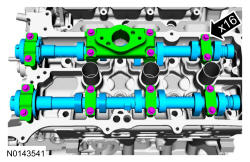
- 120.
Remove the bolts and the LH camshaft bearing caps.- Remove the LH camshafts.
NOTE:
Cylinder head camshaft bearing caps are numbered to verify that they are assembled in their original positions.
RH camshafts
- 121.
Compress the RH secondary timing chain tensioner and install a suitable lock pin to retain the tensioner in the collapsed position.
- 122.
Remove the RH VCT assembly bolt and the RH exhaust camshaft sprocket bolt.- Remove the RH VCT assembly, secondary timing chain and the RH exhaust camshaft sprocket as an assembly.
- Discard the bolts.
NOTE:
The VCT bolt and the exhaust camshaft bolt must be discarded and new ones installed. However, the exhaust camshaft washer is reusable.
- 124.
Rotate the RH camshafts counterclockwise to the neutral position.
NOTE:
The camshafts must remain in the neutral position during removal or engine damage may occur.
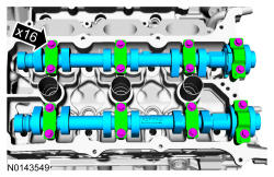
- 125.
Remove the bolts and the RH camshaft bearing caps.- Remove the RH camshafts.
NOTE:
Cylinder head camshaft bearing caps are numbered to verify that they are assembled in their original positions.