Cylinder Head - RH
WARNING: This page is about a different variant/trim than selected.
General Equipment
| 3/8" Spring Lock Coupling Disconnect Tool |
Material
| Item | Specification |
| Motorcraft ® Metal Surface Prep ZC-31-B | - |
| Motorcraft ® Silicone Gasket Remover ZC-30-A | - |
NOTE:
During engine repair procedures, cleanliness is extremely important. Any foreign material, including any material created while cleaning gasket surfaces, that enters the oil passages, coolant passages or the oil pan, may cause engine failure.
NOTE:
Whenever turbocharger air intake system components are removed, always cover open ports to protect from debris. It is important that no foreign material enter the system. The turbocharger compressor vanes are susceptible to damage from even small particles. All components should be inspected and cleaned, if necessary, prior to installation or reassembly.
- 1.
Remove the fuel rails. FUEL CHARGING AND CONTROLS - 3.5L GTDI .
- 2.
Remove the RH camshafts. Refer to Camshaft .
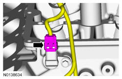
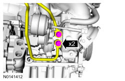
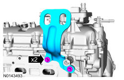
- 5.
Remove the 2 bolts and the 2 ground wire from the RH cylinder head.- Disconnect the Cylinder Head Temperature (CHT) sensor electrical connector.
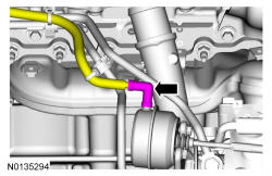
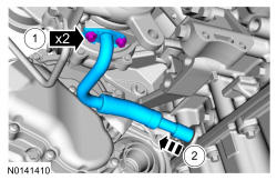
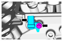
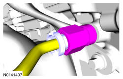
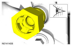
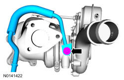
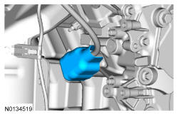
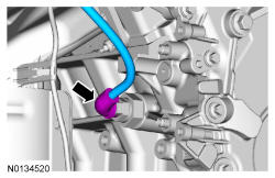
- 11.
Remove the RH turbocharger oil supply tube from the quick connect fitting. REFER to Fuel System General Information .

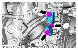
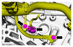
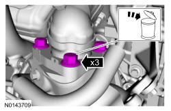
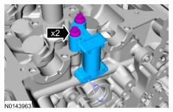
- 17.
Remove the 3 exhaust manifold-to-turbocharger bolts and the turbocharger assembly.- Discard the bolts.
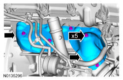
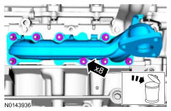
- 21.
Remove the 8 nuts and the RH exhaust manifold.- Discard the nuts.
- Clean and inspect the RH exhaust manifold. REFER to Engine System General Information .
- 22.
Remove and the 8 RH studs and discard the exhaust manifold gasket.- Discard the studs and gasket.
- Clean the exhaust manifold mating surface of the cylinder head with metal surface prep. Follow the directions on the packaging.
NOTE:
Do not use metal scrapers, wire brushes, power abrasive discs or other abrasive means to clean the sealing surfaces. These may cause scratches and gouges resulting in leak paths. Use a plastic scraper to clean the sealing surfaces.
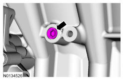
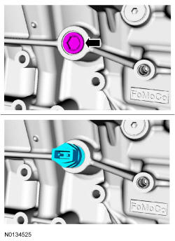
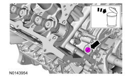
- 26.
Remove the RH cylinder block drain plug or, if equipped, the block heater.- Allow coolant to drain from the cylinder block.
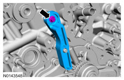
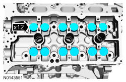
- 30.
Remove the valve tappets from the cylinder head.
NOTE:
If the components are to be reinstalled, they must be installed in the same positions. Mark the components for installation into their original locations.
- 31.
Inspect the valve tappets. REFER to Engine System General Information .
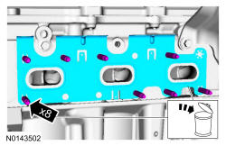
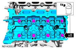
- 33.
Remove the 8 bolts from each cylinder head.- Discard the bolts.
- Remove the cylinder heads.
NOTE:
LH shown, RH similar.
NOTE:
The cylinder head bolts must be discarded and new bolts must be installed. They are a torque-to-yield design and cannot be reused.
NOTE:
Aluminum surfaces are soft and may be scratched easily. Never place the cylinder head gasket surface, unprotected, on a bench surface.
NOTE:
Place clean, lint-free shop towels over exposed engine cavities. Carefully remove the towels so foreign material is not dropped into the engine. Any foreign material (including any material created while cleaning gasket surfaces) that enters the oil passages or the oil pan, may cause engine failure.
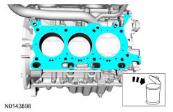
- 35.
Clean the cylinder head-to-cylinder block mating surfaces of both the cylinder heads and the cylinder block in the following sequence.- 1.
Remove any large deposits of silicone or gasket material with a plastic scraper.
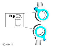
- 2.
Apply silicone gasket remover, following package directions, and allow to set for several minutes.
- 3.
Remove the silicone gasket remover with a plastic scraper. A second application of silicone gasket remover may be required if residual traces of silicone or gasket material remain.
- 4.
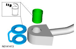
Apply metal surface prep, following package directions, to remove any remaining traces of oil or coolant and to prepare the surfaces to bond with the new gasket. Do not attempt to make the metal shiny. Some staining of the metal surfaces is normal.
- 1.
NOTE:
If there is no residual gasket material present, metal surface prep can be used to clean and prepare the surfaces.
NOTE:
Observe all warnings or cautions and follow all application directions contained on the packaging of the silicone gasket remover and the metal surface prep.
NOTE:
Do not use metal scrapers, wire brushes, power abrasive discs or other abrasive means to clean the sealing surfaces. These tools cause scratches and gouges that make leak paths. Use a plastic scraping tool to remove all traces of the head gasket.
- 36.
Support the cylinder head on a bench with the head gasket side up. Check the cylinder head distortion and the cylinder block distortion. REFER to Engine System General Information .