Section 3 (Engine - 3.5L GTDI): Installation: Camshaft
WARNING: This page is about a different variant/trim than selected.
Special Tool(s)
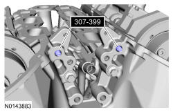
| Alignment Pins 307-399 | |
| Handle 205-153 (T80T-4000-W) | |
| Installer, Crankshaft Vibration Damper 303-102 (T74P-6316-B) | |
| Installer, Front Cover Oil Seal 303-335 | |
| Installer, Front Crankshaft Seal 303-1251 | |
| Installer, VCT Spark Plug Tube Seal 303-1247/2 | |
| Powertrain Lift 300-OTC1585AE or equivalent | |
| Tool, Camshaft Holding 303-1248 |


General Equipment
| Feeler Gauge |
| Hose Clamp Remover/Installer |
| Lock Pin |
| Strap Wrench |
Material
| Item | Specification |
| Motorcraft ® High Performance Engine RTV Silicone TA-357 | WSE-M4G323-A6 |
| Motorcraft ® Metal Surface Prep ZC-31-B | - |
| Motorcraft ® SAE 5W-30 Premium Synthetic Blend Motor Oil (US); Motorcraft ® SAE 5W-30 Super Premium Motor Oil (Canada) XO-5W30-QSP (US); CXO-5W30-LSP12 (Canada) | WSS-M2C946-A |
| Motorcraft ® Silicone Gasket Remover ZC-30-A | - |
| Motorcraft ® Thread Sealant with PTFE TA-24-B | WSK-M2G350-A2 |
Installation
WARNING:
Before beginning any service procedure in this article, refer to Safety Warnings in SERVICE INFORMATION
.
NOTE:
During engine repair procedures, cleanliness is extremely important. Any foreign material, including any material created while cleaning gasket surfaces that enters the oil passages, coolant passages or the oil pan, may cause engine failure.
NOTE:
Whenever turbocharger air intake system components are removed, always cover open ports to protect from debris. It is important that no foreign material enter the system. The turbocharger compressor vanes are susceptible to damage from even small particles. All components should be inspected and cleaned, if necessary, prior to installation or reassembly.
All camshafts
- 1.
Rotate the crankshaft counterclockwise until the crankshaft dowel pin is in the 9 o'clock position.
NOTE:
The crankshaft must remain in the freewheeling position (crankshaft dowel pin at 9 o'clock) until after the camshafts are installed and the valve clearance is checked/adjusted. Do not turn the crankshaft until instructed to do so. Failure to follow this process will result in severe engine damage.
LH camshafts
- 2.
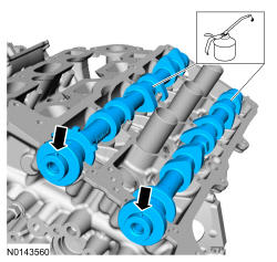
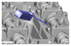
Lubricate and position the camshafts onto the LH cylinder head in the neutral position as shown.
NOTE:
The camshafts must remain in the neutral position during installation or engine damage may occur.
- 3.
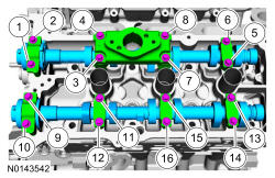
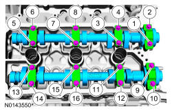
Install the 8 LH camshaft caps and the 16 bolts. Tighten the bolts in the sequence shown in the following stages:- Stage 1: Tighten bolts 1, 2, 3 and 4 to 8 Nm (71 lb-in) then an additional 45 degrees.
- Stage 2: Tighten bolts 5 and 6 to 8 Nm (71 lb-in).
- Stage 3: Tighten bolts 7 and 8 to 8 Nm (71 lb-in) then an additional 45 degrees.
- Stage 4: Loosen bolts 5 and 6.
- Tighten bolts 5 and 6 to 8 Nm (71 lb-in) then an additional 45 degrees.
- Stage 5: Tighten bolts 9, 10, 11 and 12 to 8 Nm (71 lb-in) then an additional 45 degrees.
- Stage 6: Tighten bolts 13 and 14 to 8 Nm (71 lb-in).
- Stage 7: Tighten bolts 15 and 16 to 8 Nm (71 lb-in) then an additional 45 degrees.
- Stage 8: Loosen bolts 13 and 14.
- Tighten bolts 13 and 14 to 8 Nm (71 lb-in) then an additional 45 degrees.
NOTE:
Cylinder head camshaft bearing caps are numbered to verify that they are assembled in their original positions.
RH camshafts
- 4.
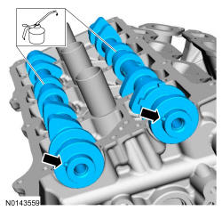
Lubricate and position the camshafts onto the RH cylinder head in the neutral position as shown.
NOTE:
The camshafts must remain in the neutral position during installation or engine damage may occur.
- 5.
Install the 8 RH camshaft caps and the 16 bolts. Tighten the bolts in the sequence shown in the following stages:- Stage 1: Tighten bolts 1, 2, 3 and 4 to 8 Nm (71 lb-in) then an additional 45 degrees.
- Stage 2: Tighten bolts 5 and 6 to 8 Nm (71 lb-in).
- Stage 3: Tighten bolts 7 and 8 to 8 Nm (71 lb-in) then an additional 45 degrees.
- Stage 4: Loosen bolts 5 and 6.
- Tighten bolts 5 and 6 to 8 Nm (71 lb-in) then an additional 45 degrees.
- Stage 5: Tighten bolts 9, 10, 11 and 12 to 8 Nm (71 lb-in) then an additional 45 degrees.
- Stage 6: Tighten bolts 13 and 14 to 8 Nm (71 lb-in).
- Stage 7: Tighten bolts 15 and 16 to 8 Nm (71 lb-in) then an additional 45 degrees.
- Stage 8: Loosen bolts 13 and 14.
- Tighten bolts 13 and 14 to 8 Nm (71 lb-in) then an additional 45 degrees.
NOTE:
Cylinder head camshaft bearing caps are numbered to verify that they are assembled in their original positions.
All camshafts
- 6.
Confirm that the valve tappet clearances are within specification. Refer to Valve Clearance Check .
NOTE:
Use a camshaft sprocket bolt to turn the camshafts.
NOTE:
If any components are installed new, the engine valve clearance must be checked/adjusted or engine damage may occur.
LH camshafts
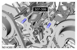
- 7.
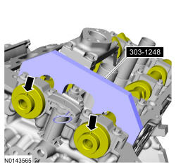
Rotate the LH camshafts to the TDC position. Install the Special Tool(s): Tool, Camshaft Holding 303-1248.
NOTE:
Use a camshaft sprocket bolt to turn the camshafts.
- 9.
Assemble the LH VCT assembly, the LH exhaust camshaft sprocket and the LH secondary timing chain.- Align the colored links with the timing marks.
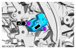
- 10.
Position the LH secondary timing assembly onto the camshafts and install the new VCT bolt and the exhaust camshaft bolt and the original washer. Tighten in 4 stages.- Stage 1: Tighten to 40 Nm (30 lb-ft).
- Stage 2: Loosen one full turn.
- Stage 3: Tighten to 10 Nm (89 lb-in).
- Stage 4: Tighten 90 degrees.
RH camshafts
- 12.
Rotate the RH camshafts to the Top Dead Center (TDC) position.Install the Special Tool(s): Tool, Camshaft Holding 303-1248.
NOTE:
Use a camshaft sprocket bolt to turn the camshafts.
- 13.
Assemble the RH Variable Camshaft Timing (VCT) assembly, the RH exhaust camshaft sprocket and the RH secondary timing chain.- Align the colored links with the timing marks.
- 14.
Position the RH secondary timing assembly onto the camshafts and install the new VCT bolt and the exhaust camshaft bolt and the original washer. Tighten in 4 stages.- Stage 1: Tighten to 40 Nm (30 lb-ft).
- Stage 2: Loosen one full turn.
- Stage 3: Tighten to 10 Nm (89 lb-in).
- Stage 4: Tighten 90 degrees.
All camshafts
- 16.
Rotate the crankshaft clockwise 60 degrees to the TDC position (crankshaft dowel pin at 11 o'clock).
- 17.
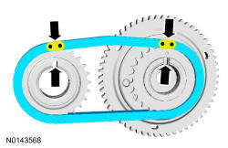
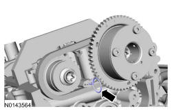
Install the primary timing chain with the colored links aligned with the timing marks on the VCT assemblies and the crankshaft sprocket.
NOTE:
The crankshaft sprocket timing mark should be between the 2 colored links.
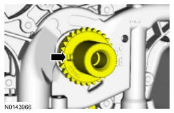
- 20.
Reset the primary timing chain tensioner.- 1.
Release the ratchet detent.
- 2.
Using a soft-jawed vise, compress the ratchet plunger.
- 3.
Align the hole in the ratchet plunger with the hole in the tensioner housing and install a suitable lockpin.
- 1.
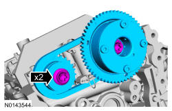
- 21.
Install the primary tensioner and the 2 bolts.- Tighten to 10 Nm (89 lb-in).
- Remove the Lock Pin.
NOTE:
It may be necessary to rotate the crankshaft slightly to remove slack from the timing chain and install the tensioner.
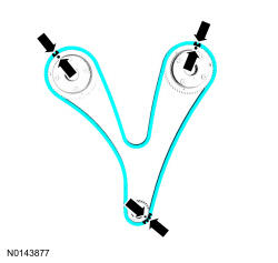
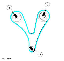
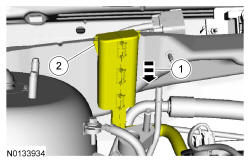
- 22.
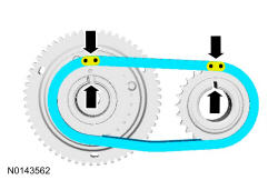
As a post-check, verify correct alignment of all timing marks.- There are 48 links between the RH intake VCT assembly colored link (1) and the LH intake VCT assembly colored link (2).
- There are 35 links between the LH intake VCT assembly colored link (2) and the 2 crankshaft sprocket colored links (3).
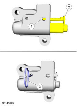
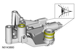
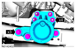
- 23.
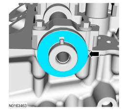
Visual check the VCT housing-to-cylinder head O-ring seals and VCT housing seals for damage and replace as necessary.
NOTE:
During removal, the O-ring seal may remain on the cylinder head. If so, remove the O-ring seal from the cylinder head, inspect the seal (replace as necessary) and install the O-ring seal on the VCT housing.
NOTE:
RH shown, LH similar.
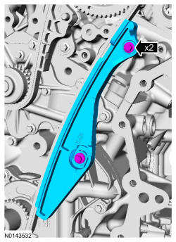
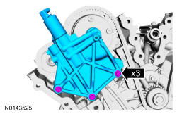
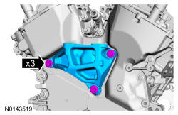
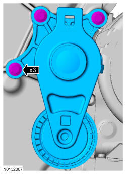
- 24.
Install the LH VCT housing and the 3 bolts.- Tighten in the sequence shown to 10 Nm (89 lb-in).
NOTE:
Make sure the dowels on the Variable Camshaft Timing (VCT) housing are fully engaged in the cylinder head prior to tightening the bolts. Failure to follow this process will result in severe engine damage.
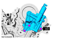
- 25.
Install the RH VCT housing and the 3 bolts.- Tighten in the sequence shown to 10 Nm (89 lb-in).
NOTE:
Make sure the dowels on the Variable Camshaft Timing (VCT) housing are fully engaged in the cylinder head prior to tightening the bolts. Failure to follow this instruction will result in severe engine damage.
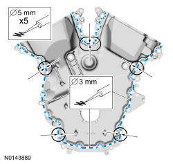
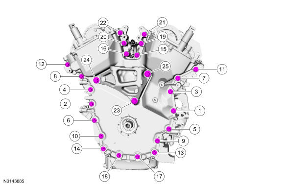
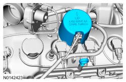
- 27.
Apply a 3.0 mm (0.11 in) bead of silicone to the engine front cover sealing surfaces including the 3 engine mount bracket bosses.- Apply a 5.5 mm (0.21 in) bead of silicone to the oil pan-to-cylinder block joint and the cylinder head-to-cylinder block joint areas of the engine front cover in 5 places as indicated.
NOTE:
The engine front cover and bolts 17, 18, 19 and 20 must be installed within 4 minutes of the initial sealant application. The remainder of the engine front cover bolts and the engine mount bracket bolts must be installed and tightened within 35 minutes of the initial sealant application. If the time limits are exceeded, the sealant must be removed, the sealing area cleaned and sealant reapplied. To clean the sealing area, use silicone gasket remover and metal surface prep. Failure to follow these instructions can cause future oil leakage.
NOTE:
Failure to use Motorcraft ® High Performance Engine RTV Silicone may cause the engine oil to foam excessively and result in serious engine damage.
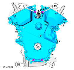
- 28.
Install the engine front cover and bolts 17, 18, 19 and 20.- Tighten in sequence to 3 Nm (27 lb-in).
NOTE:
Make sure the 2 locating dowel pins are seated correctly in the cylinder block.
- 31.
Install the remaining engine front cover bolts. Tighten all of the engine front cover bolts and engine mount bracket bolts in the sequence shown in 2 stages:- Stage 1: Tighten bolts 1 thru 22 to 10 Nm (89 lb-in) and bolts 23, 24 and 25 to 15 Nm (133 lb-in).
- Stage 2: Tighten bolts 1 thru 22 to 24 Nm (18 lb-ft) and bolts 23, 24 and 25 to 75 Nm (55 lb-ft).
NOTE:
Do not expose the Motorcraft ® High Performance Engine RTV Silicone to engine oil for at least 90 minutes after installing the engine front cover. Failure to follow this instruction may cause oil leakage.
- 32.
Install the Heated Oxygen Sensor (HO2S) connector bracket and stud bolt to the engine front cover.- Tighten to 10 Nm (89 lb-in).
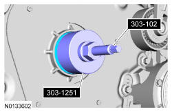
- 33.
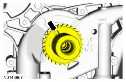
Special Tool(s): Installer, Front Crankshaft Seal 303-1251 and Installer, Crankshaft Vibration Damper 303-102 (T74P-6316-B). Install a new crankshaft front seal.
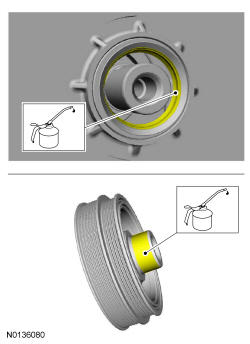
NOTE:
Apply clean engine oil to the crankshaft front seal bore in the engine front cover.
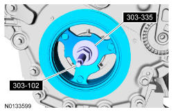
- 35.
Special Tool(s): Installer, Front Cover Oil Seal 303-335 and Installer, Crankshaft Vibration Damper 303-102 (T74P-6316-B). Install the crankshaft pulley.
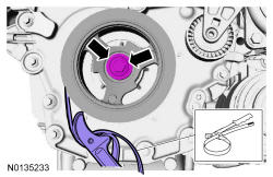
- 36.
Install the crankshaft pulley washer and new bolt and tighten in 4 stages.- Stage 1: Tighten to 120 Nm (89 lb-ft).
- Stage 2: Loosen one full turn.
- Stage 3: Tighten to 50 Nm (37 lb-ft).
- Stage 4: Tighten an additional 90 degrees.
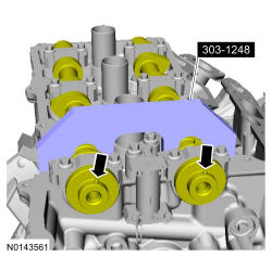
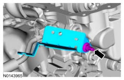
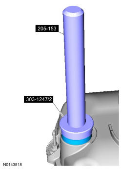
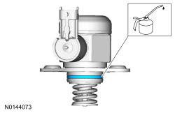
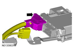
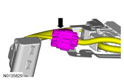
- 38.
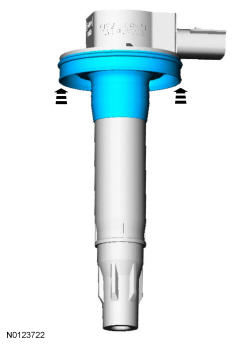
Special Tool(s): Installer, VCT Spark Plug Tube Seal 303-1247/2 and Handle 205-153 (T80T-4000-W). Install new VCT solenoid and/or spark plug tube seals.
NOTE:
Installation of new seals is only required if damaged seals were removed during disassembly of the engine.
NOTE:
VCT solenoid seal installation shown, spark plug tube seal removal similar.
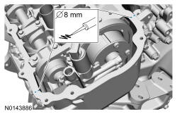
- 40.
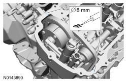
Apply an 8 mm (0.31 in) bead of silicone to the engine front cover-to-RH cylinder head joints.
NOTE:
If the valve cover is not installed and the fasteners tightened within 4 minutes, the sealant must be removed and the sealing area cleaned. To clean the sealing area, use silicone gasket remover and metal surface prep. Failure to follow these instructions can cause future oil leakage.
NOTE:
Failure to use Motorcraft ® High Performance Engine RTV Silicone may cause the engine oil to foam excessively and result in serious engine damage.
- 41.
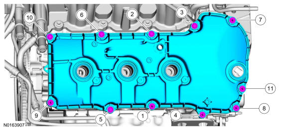
Install the RH valve cover. Tighten the 6 stud bolts and the 5 bolts.- Tighten in the sequence shown to 10 Nm (89 lb-in).
- 43.
Apply an 8 mm (0.31 in) bead of silicone to the engine front cover-to-LH cylinder head joints.
NOTE:
If the valve cover is not installed and the fasteners tightened within 4 minutes, the sealant must be removed and the sealing area cleaned. To clean the sealing area, use silicone gasket remover and metal surface prep. Failure to follow these instructions can cause future oil leakage.
NOTE:
Failure to use Motorcraft ® High Performance Engine RTV Silicone may cause the engine oil to foam excessively and result in serious engine damage.
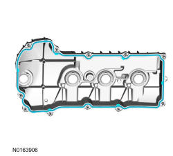
- 44.
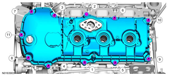
Install the LH valve cover. Tighten the 10 stud bolts and the bolt.- Tighten in the sequence shown to 10 Nm (89 lb-in).
- 45.
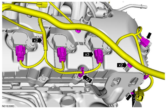
Inspect the 6 ignition coil-on-plug seals for rips, nicks or tears. Remove and discard any damaged ignition coil-on-plug seals.- Slide the new ignition coil-on-plug seal onto the ignition coil-on-plug until it is fully seated at the top of the coil-on-plug.
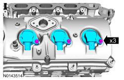
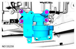
- 46.
Install the 3 RH ignition coil-on-plugs and the 3 bolts.- Tighten to 7 Nm (62 lb-in).
NOTE:
Apply a small amount of dielectric grease to the inside of the ignition coil-on-plug boots before attaching to the spark plugs.
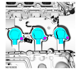
- 47.
Install the 3 LH ignition coil-on-plugs and the 3 bolts.- Tighten to 7 Nm (62 lb-in).
NOTE:
Apply a small amount of dielectric grease to the inside of the ignition coil-on-plug boots before attaching to the spark plugs.
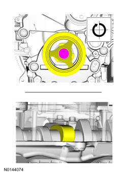
- 48.
Using the crankshaft pulley bolt, turn the crankshaft until the fuel injection pump cam lobe is at BDC.
NOTE:
The cam lobe for the fuel injection pump must be at Bottom Dead Center (BDC) for the fuel injection pump installation.
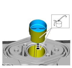
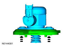
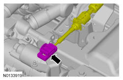
- 49.
Install the fuel injection pump roller tappet.
NOTE:
Apply clean engine oil to the tappet and bore.
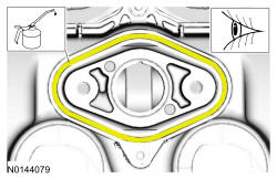
- 50.
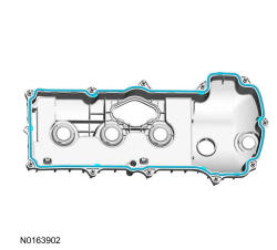
Inspect the fuel injection pump mounting plate-to-valve cover gasket and replace if necessary.
NOTE:
Apply clean engine oil to the gasket.
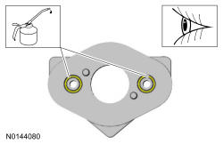
- 51.
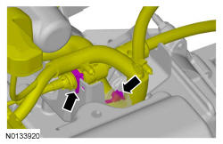
Inspect the 2 fuel injection pump mounting plate O-ring seals and replace if necessary.
NOTE:
Apply clean engine oil to the O-ring seals.
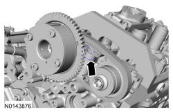
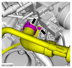
- 53.
Install the fuel injection pump mounting plate on the fuel injection pump.
NOTE:
Orient the arrow on the fuel injection pump mounting plate towards the front of the engine.
NOTE:
Make sure the mating surfaces are free of any dirt or foreign material.
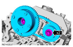
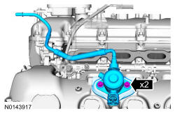
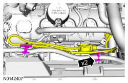
- 54.
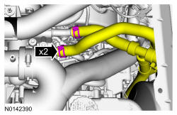
Install the fuel injection pump, mounting plate and the 2 new bolts finger-tight.- Tighten to 10 Nm (89 lb-in).
- Tighten an additional 45 degrees.
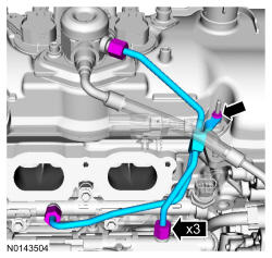
- 55.
Install the high-pressure fuel tube and tighten the 3 flare nuts in the following 3 stages.- Stage 1: Tighten to 32 Nm (24 lb-ft).
- Stage 2: Wait 10 minutes to minimize pre-stress.
- Stage 3: Tighten to 32 Nm (24 lb-ft).
- Install the new high-pressure fuel tube bracket nut.
- Tighten the nut to 8 Nm (71 lb-in).
NOTE:
To install, apply clean engine oil to the threads of the 3 high-pressure fuel tube flare nuts.
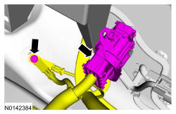
- 56.
Connect the RH VCT solenoid and the 3 ignition coil-on-plug electrical connectors.- Attach all the wiring harness retainers.
- 58.
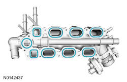
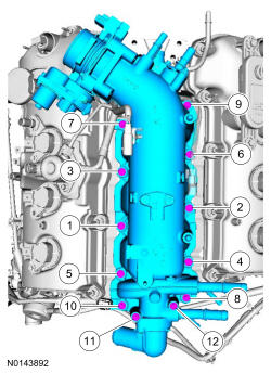
Install the intake manifold and the 12 bolts. Tighten in the sequence shown in 2 stages.- Stage 1: Tighten to 10 Nm (89 lb-in).
- Stage 2: Tighten an additional 45 degrees.
NOTE:
Installing the 2 long bolts first will aid in installing the intake manifold.
NOTE:
Make sure the fuel rail wiring harnesses are routed correct.
NOTE:
If the engine is repaired or replaced because of upper engine failure, typically including valve or piston damage, check the intake manifold for metal debris. If metal debris is found, install a new intake manifold. Failure to follow these instructions can result in engine damage.
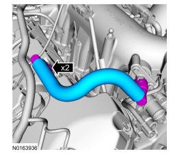
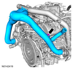
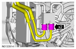
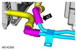
- 59.
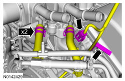
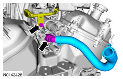
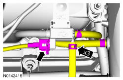
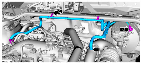
Connect the 2 turbocharger coolant hoses to the intake manifold and connect the CMP sensor electrical connector.- Attach the wiring harness retainer.
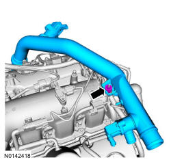
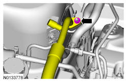
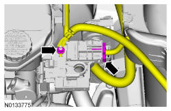
- 60.
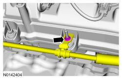
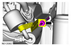
Position the fuel tube and install the fuel tube-to-engine front cover bracket bolt and install the coolant tube.- Tighten to 10 Nm (89 lb-in).
- 61.
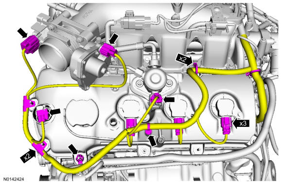
Connect the Manifold Absolute Pressure (MAP) /Intake Air Temperature 2 (IAT2) sensor electrical connector.- Connect and attach the 2 fuel injector wiring harness electrical connectors and the 2 wiring harness retainers.
- 62.
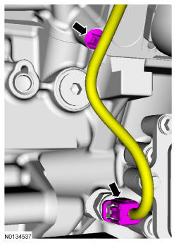
Connect the Engine Oil Pressure (EOP) electrical connector.- Attach the EOP wiring harness retainer to the engine block.
- 63.
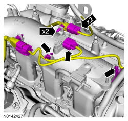
Connect the Throttle Position (TP) sensor, electronic TB, LH Variable Camshaft Timing (VCT) solenoid and the 3 ignition coil-on-plugs electrical connectors.- Attach all the wiring harness retainers from the LH valve cover and stud bolts.
- 64.
Install the noise insulator shield for the fuel injection pump and install the oil level indicator.
- 65.
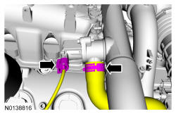
Install the PCV tube and connect the 2 quick connect couplings. REFER to Fuel System General Information .
- 67.
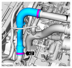
Install the RH Charge Air Cooler (CAC) tube and turbocharger intake tube as an assembly and install the RH CAC tube nut to the intake manifold.- Tighten to 6 Nm (53 lb-in).
NOTE:
The compression limiter bushing may fall out of the mounting bracket grommet on the Charge Air Cooler (CAC) tube during service. Make sure the bushing is in place when reinstalling the tube or damage to the tube may occur.
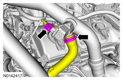
- 68.
Install the RH CAC tube to the RH turbocharger and tighten the clamp.- Tighten to 5 Nm (44 lb-in).
NOTE:
Align the index marks for the RH CAC tube.
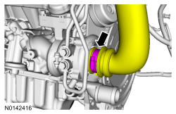
- 69.
Install the RH turbocharger intake tube and the nut.- Tighten to 6 Nm (53 lb-in).
NOTE:
The compression limiter bushing may fall out of the mounting bracket grommet on the turbocharger intake tube during service. Make sure the bushing is in place when reinstalling the tube or damage to the tube may occur.
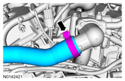
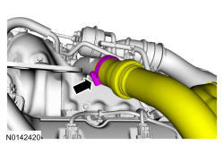
- 70.
Install the LH turbocharger intake tube to the LH turbocharger and tighten the clamp.- Tighten to 5 Nm (44 lb-in).
NOTE:
Align the index marks for the LH turbocharger intake tube.
- 71.
Install the turbocharger bypass valve hose and connect the RH turbocharger bypass valve electrical connector.
- 72.
Install the turbocharger wastegate regulating valve hoses to the RH CAC tube and turbocharger wastegate regulating valve.- Connect the turbocharger wastegate regulating valve electrical connector.
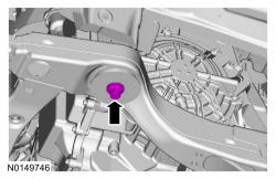
- 74.
Install the oil supply tube bracket on the LH valve cover stud bolt and install the nut.- Tighten to 8 Nm (71 lb-in).
- 75.
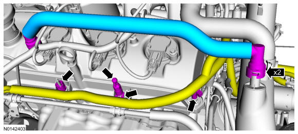
Install the crankcase vent tube and connect the 2 quick connect couplings. REFER to Fuel System General Information .- Attach the 3 wiring harness retainers and install the engine cover mounting stud.
- Tighten to 6 Nm (53 lb-in).
- Attach the 3 wiring harness retainers and install the engine cover mounting stud.
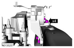
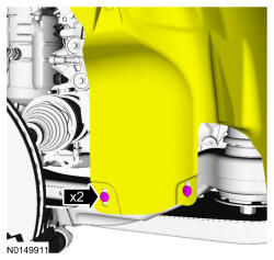
- 77.
Position the engine mount onto the engine studs and install the 4 nuts and 3 bolts hand tight.- Tighten the bolts to 90 Nm (66 lb-ft).
- Tighten the nuts to 63 Nm (46 lb-ft).
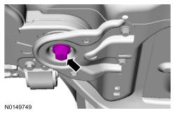
- 78.
Install the transaxle support insulator assembly the 3 nuts and the bolt.- Tighten the nuts to 63 Nm (46 lb-ft).
- Tighten the bolt to 80 Nm (59 lb-ft).
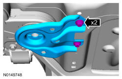
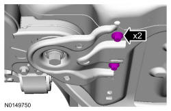
- 79.
Install the 4 transmission support insulator-to-frame rail bolts.- Tighten the 2 bottom bolts to 55 Nm (41 lb-ft).
- Tighten the 2 top bolts to 70 Nm (52 lb-ft).
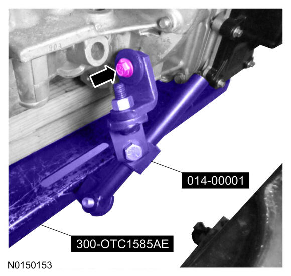
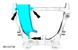
- 80.
Align the subframe and install the new front subframe bolts.- Tighten to 200 Nm (148 lb-ft).
NOTE:
RH shown, LH similar.
- 81.
Install the rear subframe brackets and the new subframe bracket-to-body bolts.- Finger tight at this stage.
NOTE:
RH shown, LH similar.
- 82.
Install the new subframe bracket bolts.- Tighten to 150 Nm (111 lb-ft).
NOTE:
RH shown, LH similar.
- 86.
Install the strut to the wheel knuckle and install the strut-to-wheel knuckle nuts and bolts.- Tighten to 250 Nm (184 lb-ft).
NOTE:
LH shown, RH similar.
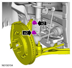
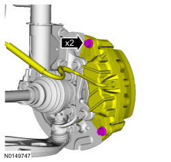
- 87.
Install the brake caliper and the guide pin bolts.- 432 mm (17 in) brakes: Tighten to 72 Nm (53 lb-ft).
- 457 mm (18 in) brakes: Tighten to 75 Nm (55 lb-ft).
NOTE:
LH shown, RH similar.
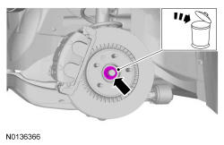
- 88.
Using the previously removed wheel hub nut, seat the LH and RH halfshafts.- Tighten to 350 Nm (258 lb-ft).
- Remove and discard the wheel hub nuts.
NOTE:
Apply the brake to keep the halfshaft from rotating.
NOTE:
LH shown, RH similar.
NOTE:
Do not tighten the wheel hub nut with the vehicle on the ground. The nut must be tightened to specification before the vehicle is lowered onto the wheels. Wheel bearing damage will occur if the wheel bearing is loaded with the weight of the vehicle applied.
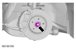
- 89.
Install a new wheel hub nuts.- Tighten to 350 Nm (258 lb-ft).
NOTE:
Apply the brake to keep the halfshaft from rotating.
NOTE:
LH shown, RH similar.
NOTE:
The wheel hub nut contains a one time locking chemical that is activated by the heat created when it is tightened. Install and tighten the new wheel hub nut to specification within 5 minutes of starting it on the threads. Always install a new wheel hub nut after loosening or when not tightened within the specified time or damage to the components can occur.
- 90.
Install the new upper stabilizer link nut.- Tighten to 150 Nm (111 lb-ft).
NOTE:
LH shown, RH similar.
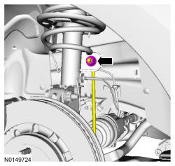
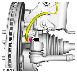
- 91.
Install the wheel speed sensor and the bolt.- Tighten to 15 Nm (133 lb-in).
NOTE:
LH shown, RH similar.
- 94.
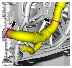
Connect the lower radiator hose to the radiator.- Attach the lower radiator hose retainer to the cooling fan and shroud.
- 95.
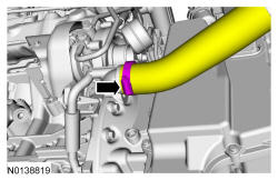
Connect the lower LH CAC tube to the LH turbocharger.- Tighten to 5 Nm (44 lb-in).
NOTE:
Align the index marks for the LH Charge Air Cooler (CAC) tube.
- 96.
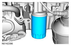
Install a new engine oil filter.- Tighten to 5 Nm (44 lb-in) and then rotate an additional 180 degrees.
NOTE:
Do not lubricate the oil filter seal.
- 97.
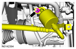
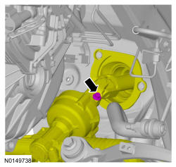
Using a new O-ring seal and gasket seal, install the upper A/C tube to the A/C compressor and install the nut.- Tighten to 15 Nm (133 lb-in).
- 98.
Install the A/C tube bracket and bolt to the rear of the A/C compressor.- Tighten to 25 Nm (18 lb-ft).
- 99.
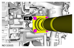
Align the index marks on the rear driveshaft to the index marks on the PTU flange made during removal and install the 4 new bolts.- Tighten to 70 Nm (52 lb-ft).
- 100.
Install the RH and LH catalytic converter. REFER to Exhaust System .
- 101.
Align and connect the steering column shaft to the steering gear and install the bolt.- Tighten to 20 Nm (177 lb-in).
NOTE:
Do not allow the intermediate shaft to rotate while it is disconnected from the gear or damage to the clockspring may occur. If there is evidence that the intermediate shaft has rotated, the clockspring must be removed and recentered. For additional information, REFER to Supplemental Restraint System
.
- 103.
Install the RH CAC tube and tighten the clamps.- Tighten to 5 Nm (44 lb-in).
NOTE:
Align the index marks for the RH CAC tube.
- 105.
Attach the wiring harness pin-type retainer and connect the transaxle control cable to the shift cable bracket.
- 107.
Install the engine wiring harness retainer to the bulkhead.- 1.
Slide the wiring harness in the bulkhead.
- 2.
Make sure the wiring harness retainer tab is below the bulkhead lip.
- 1.
- 110.
Connect the upper radiator hose to the intake manifold coolant tube. General Equipment: Hose Clamp Remover/Installer.- Install the ground wire and bolt to the engine front cover.
- Tighten to 10 Nm (89 lb-in).
- Install the ground wire and bolt to the engine front cover.
- 111.
Install the EVAP canister purge valve. REFER to Evaporative Emissions .
- 112.
Connect the fuel supply tube. REFER to Fuel System General Information .
- 114.
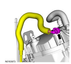
Connect the brake booster vacuum hose quick connect coupling to the intake manifold, brake booster and CAC. REFER to Fuel System General Information .- Attach the brake booster vacuum hose to strut tower brace.
- 115.
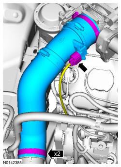
Install the CAC outlet pipe and tighten the 2 clamps.- Tighten to 5 Nm (44 lb-in).
- Connect the Turbocharger Boost Pressure (TCBP) /Charge Air Cooler Temperature (CACT) electrical connector.
NOTE:
Align the index marks for the CAC outlet pipe.
- 116.
Install the degas bottle. REFER to Engine Cooling .
- 117.
Using a new O-ring seal and gasket seal, connect the A/C tube and install the nut.- Tighten to 15 Nm (133 lb-in).
- 118.
Install the accessory dive belt. REFER to Accessory Drive .
- 120.
Install the 2 RH and 2 LH lower pin-type retainers for the engine splash shields.
NOTE:
RH shown, LH similar.
- 121.
Install the front wheels and tires. REFER to Wheels and Tires .
- 122.
Connect the engine wiring harness electrical connector and install the ground wires and the retainer.- Tighten to 10 Nm (89 lb-in).
- 123.
Connect the battery power feed wire to the positive battery terminal and install the nut.- Connect the electrical connector.
- Tighten to 6 Nm (53 lb-in).
- 124.
Install the battery tray. REFER to Battery, Mounting and Cables .
- 125.
Install the engine ACL and ACL outlet pipe. REFER to Intake Air Distribution and Filtering .
- 126.
Install the cowl panel. REFER to Front End Body Panels .
- 128.
Fill and bleed the cooling system. REFER to Engine Cooling .
- 129.
Recharge the A/C system. REFER to Climate Control DATC or REFER to Climate Control EMTC .