Component Description
Heating Ventilation Air Conditioning (HVAC) Module - EMTC
The EMTC system uses a remote HVAC module that is separate from the control interface. For details on the HVAC module communication, refer to CLIMATE CONTROL - EMTC , Control System Logic.
The HVAC module also controls the outputs for the interior ambient lighting, rear window defrost and heated seats.
The HVAC module utilizes an FET protective circuit strategy for its actuator outputs. Output load (current level) is monitored for excessive current (typically short circuits) and is shut down (turns off the voltage or ground provided by the module) when a fault event is detected. A short circuit DTC is stored at the fault event and a cumulative counter is started.
When the demand for the output is no longer present, the module resets the FET circuit protection to allow the circuit to function. The next time the driver requests a circuit to activate that has been shut down by a previous short (Field-Effect Transistor (FET) protection) and the circuit is still shorted, the FET protection shuts off the circuit again and the cumulative counter advances.
When the excessive circuit load occurs often enough, the module shuts down the output until a repair procedure is carried out. The FET protected circuit has 3 predefined levels of short circuit tolerance based on the harmful effect of each circuit fault on the FET and the ability of the FET to withstand it. A module lifetime level of fault events is established based upon the durability of the FET. If the total tolerance level is determined to be 600 fault events, the 3 predefined levels would be 200, 400 and 600 fault events.
When each tolerance level is reached, the short circuit DTC that was stored on the first failure cannot be cleared by a command to clear the DTCs. The module does not allow the DTC to be cleared or the circuit to be restored to normal operation until a successful self-test proves that the fault has been repaired. After the self-test has successfully completed (no on-demand DTCs present), DTC U1000:00 and the associated DTC (the DTC related to the shorted circuit) automatically clears and the circuit function returns.
When each level is reached, the DTC associated with the short circuit sets along with DTC U1000:00. These DTCs can be cleared using the module self-test, then the Clear DTC operation on the scan tool. The module never resets the fault event counter to zero and continues to advance the fault event counter as short circuit fault events occur.
If the number of short circuit fault events reach the third level, then DTCs U1000:00 and U3000:49 set along with the associated short circuit DTC. DTC U3000:49 cannot be cleared and a new module must be installed after the repair.
The HVAC requires PMI when it is replaced.
Ambient Air Temperature Sensor
The AAT sensor is an input to the PCM. If the temperature is below a predetermined value, the PCM does not allow the A/C clutch to engage.
Air Conditioning (AC) Pressure Transducer
The PCM monitors the discharge pressure measured by the A/C pressure transducer. As the refrigerant pressure changes, the resistance of the A/C pressure transducer changes. It is not necessary to recover the refrigerant before removing the A/C pressure transducer.
Evaporator Temperature Sensor
The evaporator temperature sensor contains a thermistor. The sensor varies its resistance with the temperature. As the temperature rises, the resistance falls. As the temperature falls, the resistance rises. The evaporator temperature sensor is an input to the HVAC module and the information is relayed to the PCM over the HS-CAN. If the temperature is below a predetermined value, the PCM does not allow the A/C clutch to engage.
In-Vehicle Temperature and Humidity Sensor
The in-vehicle temperature and humidity sensor contains a thermistor and a sensing element which separately measure the in-vehicle air temperature and humidity and sends those readings to the HVAC module. The in-vehicle temperature and humidity sensor has an electric fan within the sensor that draws in-vehicle air across the two sensing elements.
Defrost-Panel-Floor Mode Door Actuator
The defrost/panel/floor mode door actuator contains a reversible electric motor and potentiometer. The potentiometer allows the HVAC module to monitor the position of the airflow mode door.
Temperature Blend Door Actuator
The temperature blend door actuator contains a reversible electric motor and potentiometer. The potentiometer allows the HVAC module to monitor the position of the temperature blend door.
Air inlet Mode Door Actuator
The air inlet mode door actuator contains a reversible electric motor and potentiometer. The potentiometer allows the HVAC module to monitor the position of the air inlet mode door.
Blower Motor Speed Control
The HVAC module sends a PWM signal to the blower motor speed control to control the blower speed. The blower speed control provides variable ground feed for the blower motor to control the speed. A delay function provides a gradual increase or decrease in blower motor speed under all conditions.
Air Conditioning (AC) Compressor Clutch
When battery voltage is applied to the A/C compressor clutch field coil, the magnetic force locks the clutch plate and hub assembly and the A/C clutch pulley together as one unit, causing the compressor shaft to rotate.
Internally Controlled Variable Displacement Compressor
Variable displacement compressor internals are similar to fixed displacement compressors. The pistons are placed around an angled plate (swash plate) and are pushed back and forth as the plate rotates. Variable displacement compressors vary the swash plate angle to allow piston displacement to vary from 5% (default) to 100% of full capacity to meet cooling demand.
The internally controlled variable displacement compressor has the following characteristics:
- A non-serviceable shaft seal.
- A non-serviceable pressure relief valve installed in the rear of the compressor to protect the refrigerant system against excessively high refrigerant pressures.
- Uses Motorcraft® Polyalkylene Glycol (PAG) Refrigerant Compressor Oil YN-12-D. This oil contains special additives required for the A/C compressor. The oil may have some slightly dark-colored streaks while maintaining normal oil viscosity. This is normal for this A/C compressor because of break-in wear that can discolor the oil.
Refer to the oil adding procedure specified for this vehicle when installing a new A/C compressor. Refrigerant Oil Adding
The piston displacement of the internally controlled variable displacement compressor is controlled with a bellows actuated control valve located in the compressor rear head. The control valve senses the refrigerant suction and head pressures and regulates the pressure in the crankcase. Swash plate angle is a result of the balance of the crankcase pressure on one side of the pistons and suction and head pressure on the other side. The suction pressure varies with the evaporator core temperature. The valve regulates the amount of refrigerant being discharged by an optimum compressor displacement, resulting in the requested evaporator core temperature of approximately 3°C (37.4°F).
Externally Controlled Variable Displacement Compressor
Variable displacement compressor internals are similar to fixed displacement compressors. The pistons are placed around an angled plate (swash plate) and are pushed back and forth as the plate rotates. Variable displacement compressors vary the swash plate angle to allow piston displacement to vary from 5% (default) to 100% of full capacity to meet cooling demand.
The externally controlled variable displacement compressor has the following characteristics:
- A non-serviceable shaft seal.
- A non-serviceable pressure relief valve installed in the rear of the compressor to protect the refrigerant system against excessively high refrigerant pressures.
- Uses Motorcraft® Polyalkylene Glycol (PAG) Refrigerant Compressor Oil YN-12-D. This oil contains special additives required for the A/C compressor. The oil may have some slightly dark-colored streaks while maintaining normal oil viscosity. This is normal for this A/C compressor because of break-in wear that can discolor the oil.
Refer to the oil adding procedure specified for this vehicle when installing a new A/C compressor. Refrigerant Oil Adding
The piston displacement of the externally controlled variable displacement compressor is controlled by a PWM signal from the PCM which electronically drives the control valve. The control valve drives the crankcase pressure and thus the swash plate angle. The externally controlled variable displacement compressor achieves precise cooling capability based on the cabin temperature and driving conditions, resulting in the target evaporator core temperature. The target evaporator core temperature range for the DATC system is 3-8°C (37.4-46.4°F); 3-5°C (37.4-41°F) for the EMTC system.
The PCM pulse width modulates the ground to the externally controlled variable displacement compressor control valve to change the A/C compressor displacement by changing the swash plate angle based on the following items:
- Ambient air temperature
- Engine revolutions per minute (RPM)
- Evaporator temperature
- High side and low side A/C pressures
- Temperature and mode settings of the climate control head
Air Conditioning (A/C) Condenser
The A/C condenser is an aluminum fin-and-tube design heat exchanger.
For Ti-VCT engine equipped vehicles the receiver-drier is integral to the A/C condenser.
Evaporator Core
The evaporator core is an aluminum plate/fin type and is located in the heater core and evaporator core housing.
Thermostatic Expansion Valve (TXV)
The TXV provides a restriction to the flow of refrigerant from the high-pressure side of the refrigerant system and separates the low-pressure and high-pressure sides of the refrigerant system. Refrigerant entering and exiting the evaporator core passes through the TXV through 2 separate flow paths. An internal temperature sensing bulb senses the temperature of the refrigerant flowing out of the evaporator core and adjusts an internal pin-type valve to meter the refrigerant flow into the evaporator core. The internal pin-type valve decreases the amount of refrigerant entering the evaporator core at lower temperatures and increases the amount of refrigerant entering the evaporator core at higher temperatures.
Receiver-Drier
The receiver-drier stores high-pressure liquid and the desiccant bag mounted inside the receiver-drier removes any retained moisture from the refrigerant.
For GTDI engine equipped vehicles, the receiver-drier is mounted between the A/C condenser outlet and the TXV manifold and tube assembly.
For Ti-VCT engine equipped vehicles, the receiver-drier is incorporated onto the LH side of the A/C condenser. The receiver-drier desiccant bag is a separate component and can be removed and installed with the A/C condenser in the vehicle.
Service Gauge Port Valves
The service gauge port valve is an integral part of the refrigerant line or component.
- Prior to leak testing, blow air over service gauge port valves to insure an accurate test.
- Special couplings are required for both the high-side and low-side service gauge port valves.
- A very small amount of leakage around the Schrader-type valve with the service gauge port valve cap removed is considered normal. Install a new Schrader-type valve core if the seal leaks excessively.
- The A/C service gauge port valve caps are used as primary seals in the refrigerant system to prevent leakage through the Schrader-type valves from reaching the atmosphere. Always install and tighten the A/C service gauge port valve caps to the correct torque after they are removed.
- Follow the procedure and the notes for electronic leak testing. Refer to: Electronic Leak Detection
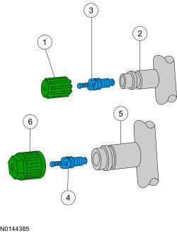
| Item | Description | Torque |
|---|---|---|
| 1 | Low-pressure service gauge port valve cap | 0.8 Nm (7 lb-in) |
| 2 | Low-pressure service gauge port valve | - |
| 3 | Low-pressure Schrader-type valve | 2.26 Nm (20 lb-in) |
| 4 | High-pressure Schrader-type valve | 3.4 Nm (30 lb-in) |
| 5 | High-pressure service gauge port valve | - |
| 6 | High-pressure service gauge port valve cap | 0.8 Nm (7 lb-in) |
Refrigerant System Dye
A fluorescent refrigerant system dye wafer is added to the receiver-drier desiccant bag to assist in refrigerant system leak diagnosis using a Rotunda-approved UV blacklight. This fluorescent dye wafer dissolves after about 30 minutes of continued A/C operation. It is not necessary to add additional dye to the refrigerant system before diagnosing leaks, even if a significant amount of refrigerant has been removed from the system.
Cabin Air Filter
The vehicle is factory equipped with a cabin air filter. The cabin air filter is positioned at the blower motor inlet and filters both fresh and recirculated air.
A cabin air filter must be installed at all times to prevent foreign objects from entering the system. Running the system without a filter in place could result in degradation or damage to the system. The cabin air filter must be installed for correct climate control system NVH performance.
Access the cabin air filter by removing the glove compartment and the cabin air filter access cover.