Mechanical Procedures
Illustrations in this service information may be used instead of written step instructions. Color-coding (see color scheme illustration) is used to communicate the required step action or actions. Service action icons may be used to add information regarding the required action.
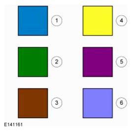
| 1 | Blue - Target or primary component to be removed/installed (or disassembled/assembled). |
| 2 | Green - Components that need to be removed prior to or installed after the target/primary. |
| 3 | Brown - Components that need to be removed prior to or installed after the target/primary. |
| 4 | Yellow - Components to be set aside for access, but not removed. Also highlighted areas to inspect or adjust. |
| 5 | Magenta - Electrical connectors and fasteners such as nuts, bolts, clamps, or clips to be: detached, attached, loosened, moved, removed or installed. |
| 6 | Pale Blue - Special tool(s), general equipment, or common tools used in an uncommon way. |
Other color coding
- Alternating Blue and White
- Chemical, adhesive or sealer apply areas
- Red
- Sectioned or cut-away areas
- Grey
- Background components shown for location information