Pyrotechnic Device Disposal
Disposal of Deployable Devices and Pyrotechnic Devices That Are Undeployed-Inoperative
- 1.
Depower the SRS. Refer to Supplemental Restraint System (SRS) Depowering and Repowering - With Intelligent Access (IA) or Supplemental Restraint System (SRS) Depowering and Repowering - Without Intelligent Access (IA) .
- 2.
Remove the undeployed/inoperative device. Refer to the appropriate procedure in this service information or refer to REFER to Safety Belt System .
- 3.NOTE: When installing a new air bag module or inflatable safety belt inflator, a prepaid return postcard is provided with the replacement part. The serial number for the new part and the VIN must be recorded and sent to Ford Motor Company.
If installing a new air bag module or inflatable safety belt inflator, record the necessary information and return the inoperative air bag module to Ford Motor Company.
Disposal of Deployable Devices and Pyrotechnic Devices That Are Deployed
- 1.
Depower the SRS. Refer to Supplemental Restraint System (SRS) Depowering and Repowering - With Intelligent Access (IA) or Supplemental Restraint System (SRS) Depowering and Repowering - Without Intelligent Access (IA) .
- 2.
Remove the deployed device. Refer to the appropriate procedure in this service information or REFER to Safety Belt System .
- 3.NOTE: If a dual stage driver or passenger air bag module has deployed due to a crash event, the air bag module requires manual deployment to make sure both stages and the active canister vent have deployed before scrapping the vehicle or disposing of the air bag module. To determine if a vehicle is equipped with dual stage driver or passenger air bag modules, refer to Supplemental Restraint System (SRS) , Component Description.
Dispose of the deployed device in the same manner as any other part to be scrapped.
Disposal of Deployable Devices and Pyrotechnic Devices That Require Manual Deployment
- 1.NOTE: To determine the deployable devices a vehicle is equipped with, refer to Supplemental Restraint System (SRS) , Component Location.
A vehicle equipped with any of the following deployable devices requires manual deployment of the devices before scrapping the vehicle or component. For additional information, refer to the appropriate portion of this procedure.
- Driver air bag module
- Inflatable safety belt inflators
- Knee air bag module
- Passenger air bag module
- Seat side air bag modules
- Safety Canopy
- Side air curtain modules
- 2.NOTE: To determine the pyrotechnic devices a vehicle is equipped with, refer to Supplemental Restraint System (SRS) , Component Location.
A vehicle equipped with any of the following pyrotechnic devices requires manual deployment of the devices before scrapping the vehicle or component. For additional information, refer to the appropriate portion of this procedure.
- Inflatable safety belt inflators
- Safety belt buckle pretensioners
- Safety belt retractor pretensioners
- Safety belt anchor pretensioners
- Adaptive load-limiting retractors
- Deployable steering column
- 3.NOTE: To determine if a vehicle is equipped with dual stage driver or passenger air bag modules, refer to Supplemental Restraint System (SRS) , Component Description.
If a dual stage driver or passenger air bag module has deployed due to a crash event, the air bag module requires manual deployment to make sure both stages and the active canister vent have deployed before scrapping the vehicle or disposing of the air bag module. Refer to Pyrotechnic Device Disposal , Driver, Passenger, Knee and Seat Side Air Bag Modules - Remote Deployment.
Driver, Passenger, Knee and Seat Side Air Bag Modules - Remote Deployment
If a front air bag module has deployed, it is mandatory that the front air bag module be remotely deployed using the appropriate air bag disposal procedure.
- 1.
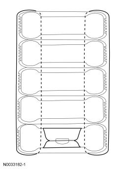
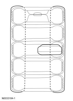
Make a container to house the air bag module for deployment.- Obtain a tire and wheel assembly and 4 additional tires (without wheels) of the same size.
NOTE: The tires must be of sufficient size to accommodate the air bag module.- With the tire and wheel assembly on the bottom, stack the tires.
- Securely tie all of the tires together.
- 2.
Depower the SRS. Refer to Supplemental Restraint System (SRS) Depowering and Repowering - With Intelligent Access (IA) or Supplemental Restraint System (SRS) Depowering and Repowering - Without Intelligent Access (IA) .
- 3.
Remove the air bag module. For additional information, refer to the appropriate procedure in this service information.
- 4.NOTE: If the air bag module does not have a hard-wired pigtail, cut the wires and connector(s) from the vehicle wire harness and reconnect to the air bag module.
Cut each of the air bag module wires near the electrical connector that connects to the vehicle wire harness.
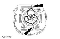
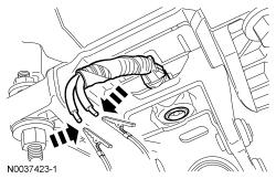
- 6.NOTE: Typical driver air bag module with 2 loops shown in illustration, other air bag modules with multiple loops or multiple features (canister vent, active tether) similar.
For air bag modules with multiple loops, twist together a wire from each loop then repeat for the remaining wires from each loop.
- 7.
Make a jumper harness to deploy the air bag module.- Obtain 2 wires (20 gauge minimum) at least 9.14 m (30 ft).
- At one end of the jumper harness, connect the wires together.
- 8.
Using the end of the jumper harness where the wires are not connected together, attach each wire of the jumper harness to each wire of the air bag module or to the twisted-together wires if multiple loops. Use tape or other insulating material to make sure the leads do not make contact with each other.
- 9.NOTE: Make sure the air bag module connections are maintained.
For driver air bag modules, with the stack of tires upright and the wheel on the bottom, carefully place the driver air bag module, with the trim cover facing up, on the wheel.
- 10.NOTE: Make sure the air bag module connections are maintained.
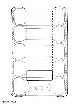
For passenger, knee and seat side air bag modules:
- tip the stack of tires on its side
- place the air bag module inside the center tire, making sure that there are 2 tires beneath the tire containing the air bag module and 2 tires (including the tire and wheel assembly) above the tire containing the air bag module
- place the tire stack upright, with the wheel on top
- 12.
From the end of the jumper harness that is not connected to the air bag module, disconnect the 2 wires of the jumper harness from each other.
- 13.
Deploy the air bag module by touching the ends of the 2 wires of the jumper harness to the terminals of a 12-volt battery.
Safety Belt Retractor-Buckle Pretensioners, Adaptive Load Limiting Retractors and Safety Belt Inflators - Remote Deployment
- 1.
Make a container to house the safety belt buckle, retractor or inflator for deployment.- Obtain a tire and wheel assembly and 4 additional tires (without wheels) of the same size.
NOTE: The tires must be of sufficient size to accommodate the safety belt buckle, retractor or inflator.- With the tire and wheel assembly on the bottom, stack the tires.
- Securely tie all of the tires together.
- 2.
Depower the SRS. Refer to Supplemental Restraint System (SRS) Depowering and Repowering - With Intelligent Access (IA) or Supplemental Restraint System (SRS) Depowering and Repowering - Without Intelligent Access (IA) .
- 3.
Remove the safety belt buckle, retractor or inflator. REFER to Safety Belt System for the appropriate procedure.- When deploying a safety belt buckle pretensioner, install a nut and bolt of sufficient length and the same diameter used to retain it to the seat.
- 4.NOTE: If the safety belt anchor, buckle, retractor or inflator does not have a hard-wired pigtail, cut the wires and connector(s) from the vehicle wire harness and reconnect to the safety belt buckle, retractor or inflator.
Cut each of the safety belt anchor, buckle, retractor or inflator wires near the electrical connector that connects to the vehicle wire harness.
- 6.
Make a jumper harness to deploy the safety belt buckle, retractor or inflator.- Obtain 2 wires (20 gauge minimum) at least 9.14 m (30 ft) long and strip both ends of each wire.
- At one end of the jumper harness, connect the wires together.
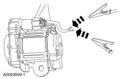
- 7.NOTE: Typical safety belt retractor pretensioner shown in illustration, other safety belt anchor pretensioners, buckle pretensioners, load-limiting retractors and safety belt inflators similar.
Using the end of the jumper harness where the wires are not connected together, attach each wire of the jumper harness to each wire of the safety belt anchor, buckle, retractor or inflator. Use tape or other insulating material to make sure the leads do not make contact with each other.
- 8.NOTE: Make sure the safety belt anchor, buckle, retractor or inflator connections are maintained.
Tip the stack of tires on its side and place the safety belt anchor, buckle, retractor or inflator inside the center tire, making sure that there are 2 tires beneath the tire containing the safety belt anchor, buckle, retractor or inflator and 2 tires (including the tire and wheel assembly) above the tire containing the safety belt anchor, buckle, retractor or inflator.
- 11.
From the end of the jumper harness that is not connected to the safety belt anchor, buckle, retractor or inflator, disconnect the 2 wires of the jumper harness from each other.
- 12.
Deploy the safety belt anchor, buckle, retractor or inflator by touching the ends of the 2 wires of the jumper harness to the terminals of a 12-volt battery.
- 13.
To allow for cooling, wait at least 10 minutes before approaching the deployed safety belt anchor, buckle, retractor or inflator.
- 14.
Dispose of the deployed safety belt anchor, buckle, retractor or inflator in the same manner as any other part to be scrapped.
Safety Belt Retractor-Buckle Pretensioners and Adaptive Load Limiting Retractors - In-Vehicle Deployment
- 1.
Depower the SRS. Refer to Supplemental Restraint System (SRS) Depowering and Repowering - With Intelligent Access (IA) or Supplemental Restraint System (SRS) Depowering and Repowering - Without Intelligent Access (IA) .
- 2.
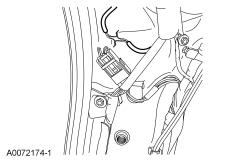
Access the safety belt anchor, buckle or retractor electrical connectors. REFER to Safety Belt System
- 3.
Cut each of the safety belt anchor, buckle or retractor wires, leaving at least 101.6 mm (4 in) to work with.
- 5.
Make a jumper harness to deploy the safety belt anchor, buckle or retractor.- Obtain 2 wires (20 gauge minimum) at least 9.14 m (30 ft) long and strip both ends of each wire.
- At one end of the jumper harness, connect the wires together.
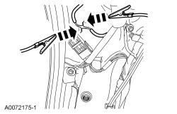
- 6.NOTE: Typical safety belt retractor pretensioner shown in illustration, other safety belt anchor pretensioners, buckle pretensioners and load-limiting retractors are similar.
Using the end of the jumper harness where the wires are not connected together, attach each wire of the jumper harness to each wire of the safety belt anchor, buckle or retractor. Use tape or other insulating material to make sure the leads do not make contact with each other.
- 8.
From the end of the jumper harness that is not connected to the safety belt anchor, buckle or retractor, disconnect the 2 wires of the jumper harness from each other.
- 9.
Deploy the safety belt anchor, buckle or retractor by touching the ends of the 2 wires of the jumper harness to the terminals of a 12-volt battery.
- 10.
To allow for cooling, wait at least 10 minutes before approaching the deployed safety belt anchor, buckle or retractor.
- 11.
Dispose of the deployed safety belt anchor, buckle or retractor in the same manner as any other part to be scrapped.
Safety Canopy and Side Air Curtain Modules - In-Vehicle Deployment
- 1.
Depower the SRS. Refer to Supplemental Restraint System (SRS) Depowering and Repowering - With Intelligent Access (IA) or Supplemental Restraint System (SRS) Depowering and Repowering - Without Intelligent Access (IA) .
- 2.
Access the Safety Canopy/side air curtain module electrical connectors. For additional information, refer to the appropriate procedure in this service information.
- 3.
Cut each of the Safety Canopy/side air curtain module wires leaving at least 101.6 mm (4 in) to work with.
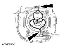
- 5.NOTE: Typical Safety Canopy/side air curtain module with 2 loops shown in illustration, other Safety Canopy/side air curtain modules with 2 loops are similar.
For Safety Canopy/side air curtain modules with multiple loops, twist together a wire from each loop then repeat for the remaining wires from each loop.
- 6.
Make a jumper harness to deploy the Safety Canopy/side air curtain module.- Obtain 2 wires (20 gauge minimum) at least 9.14 m (30 ft) long and strip both ends of each wire.
- At one end of the jumper harness, connect the wires together.
- 7.
Using the end of the jumper harness where the wires are not connected together, attach each wire of the jumper harness to each wire of the Safety Canopy/side air curtain module or to the twisted-together wires if multiple loops. Use tape or other insulating material to make sure the leads do not make contact with each other.
- 8.
From the end of the jumper harness that is not connected to the Safety Canopy/side air curtain module, disconnect the 2 wires of the jumper harness from each other.
- 9.
Deploy the Safety Canopy/side air curtain module by touching the ends of the 2 wires of the jumper harness to the terminals of a 12-volt battery.
- 10.
To allow for cooling, wait at least 10 minutes before approaching the deployed Safety Canopy/side air curtain module.
- 11.
Dispose of the deployed Safety Canopy/side air curtain module in the same manner as any other part to be scrapped.
Deployable Steering Column - In-Vehicle Deployment
- 1.
Depower the SRS. Refer to Supplemental Restraint System (SRS) Depowering and Repowering - With Intelligent Access (IA) or Supplemental Restraint System (SRS) Depowering and Repowering - Without Intelligent Access (IA) .
- 2.NOTE: It may be necessary to lower or remove the deployable steering column from the instrument panel to access the deployable steering column electrical connector.
Access the deployable steering column electrical connector.
- 3.NOTE: If the deployable steering column does not have a hard-wired pigtail, cut the wires and connector(s) from the vehicle wire harness and reconnect to the deployable steering column.
Cut each of the deployable steering column wires, leaving at least 101.6 mm (4 in) to work with.
- 5.
Make a jumper harness to deploy the deployable steering column.- Obtain 2 wires (20 gauge minimum) at least 9.14 m (30 ft) long and strip both ends of each wire.
- At one end of the jumper harness, connect the wires together.
- 6.
Using the end of the jumper harness where the wires are not connected together, attach each wire of the jumper harness to each wire of the deployable steering column. Use tape or other insulating material to make sure the leads do not make contact with each other.
- 8.
From the end of the jumper harness that is not connected to the deployable steering column, disconnect the 2 wires of the jumper harness from each other.