Auxiliary Climate Control: Notes
Component Location

| Item | Description |
|---|---|
| 1 | Auxiliary blower motor |
| 2 | Auxiliary blower motor speed control |
| 3 | Auxiliary temperature blend door actuator |
| 4 | Auxiliary mode door actuator |
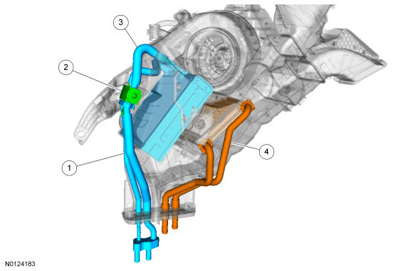
| Item | Description |
|---|---|
| 1 | Auxiliary evaporator outlet and inlet jumper lines |
| 2 | Auxiliary TXV |
| 3 | Auxiliary evaporator core |
| 4 | Auxiliary heater core |
Overview
- The A/C refrigerant of all vehicles must be identified and analyzed prior to refrigerant charging. Failure to do so can contaminate the shop bulk refrigerant and other vehicles.
- Do not add R-12 refrigerant to an A/C system that requires the use of R-134a refrigerant. These 2 types of refrigerant must never be mixed. Doing so can damage the A/C system.
- Charge the A/C system with R-134a refrigerant gas while the engine is running only at the low-pressure side to prevent refrigerant slugging from damaging the A/C compressor.
- Use only R-134a refrigerant. Due to environmental concerns, when the A/C system is drained, the refrigerant must be collected using refrigerant recovery/recycling equipment. Federal, State/Provincial and/or local laws REQUIRE that R-134a be recovered into appropriate recovery equipment and the process be conducted by qualified technicians who have been certified by an approved organization, such as ASE or MACS. Use of a recovery machine dedicated to R-134a is necessary to reduce the possibility of oil and refrigerant incompatibility concerns. Refer to the instructions provided by the equipment manufacturer when removing refrigerant from or charging the A/C system.
- Refrigerant R-134a must not be mixed with air for leak testing or used with air for any other purpose above atmospheric pressure. R-134a is combustible when mixed with high concentrations of air and higher pressures.
- A number of manufacturers are producing refrigerant products that are described as direct substitutes for refrigerant R-134a. The use of any unauthorized substitute refrigerant can severely damage the A/C components. If repair is required, use only new or recycled refrigerant R-134a.
- Never open or loosen a connection before recovering the refrigerant.
- When loosening a connection, if any residual pressure is evident, allow it to leak out before opening the fitting.
- Evacuate a system that has been opened to install a new component or one that has discharged through leakage before charging.
- Seal open fittings with a cap or plug immediately after disconnecting a component from the system.
- Clean the outside of the fittings thoroughly before disconnecting a component from the system.
- Do not remove the sealing caps from a new component until ready to install.
- Refrigerant oil will absorb moisture from the atmosphere if left uncapped. Do not open an oil container until ready to use and install the cap immediately after using. Store the oil in a clean, moisture-free container.
- Install a new O-ring seal before connecting an open fitting. Coat the fitting and O-ring seal with PAG oil before connecting.
- When installing a refrigerant line, avoid sharp bends. Position the line away from the exhaust or any sharp edges that can chafe the line.
- Tighten threaded fittings only to specifications. The steel and aluminum fittings used in the refrigerant system will not tolerate overtightening.
- When disconnecting a fitting, use a wrench on both halves of the fitting to prevent twisting of the refrigerant lines or tubes.
- Do not open a refrigerant system or uncap a new component unless it is as close as possible to room temperature. This will prevent condensation from forming inside a component that is cooler than the surrounding air.
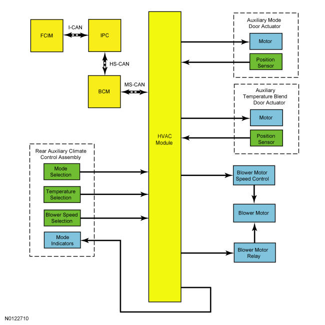
An auxiliary climate control system is available as optional equipment. The auxiliary climate control system operation is determined by the settings on the front or rear auxiliary climate control assembly. The auxiliary climate control assemblies include a blower motor switch and temperature control/air distribution mode knob, neither of which can be individually serviced.
Auxiliary blower motor operation is enabled when the HVAC system is in any mode except OFF. The auxiliary system air can be cooled below interior air temperature only when A/C compressor operation has been requested by the settings of the climate control assembly of the base (front) system. The auxiliary system air can be heated at any time.
System Operation
System Diagram
Network Message Chart
Module Network Input Messages - FCIM
| Broadcast Message | Originating Module | Message Purpose |
|---|---|---|
| Climate control touch screen and voice requests | APIM | This message contains both the climate control system voice commands as well as all climate control system touch screen inputs. |
| Climate control status | HVAC Module | This message contains the HVAC mode status for the mode indicators. |
Module Network Input Messages - APIM
| Broadcast Message | Originating Module | Message Purpose |
|---|---|---|
| Climate control status | HVAC Module | This message contains the HVAC climate control settings for the touch screen display. |
Module Network Input Messages - HVAC Module
| Broadcast Message | Originating Module | Message Purpose |
|---|---|---|
| Climate control requests (gateway) | FCIM | This message contains all climate control system controls requests except blower motor speed. |
| Climate control seat requests (gateway) | FCIM | This message contains the climate control system controls request for blower motor speed. |
Auxiliary Climate Controls
The Front Auxiliary Climate Controls
The blower motor speed can be set to OFF, LO, MED-LO, MED-HI or HI by pressing the auxiliary blower FAN "+" or "-" button. The temperature/airflow mode can be adjusted by pressing the rear TEMPERATURE "+" or "-" button. If the front (main) driver side temperature is set to full COOL or full HEAT, the auxiliary temperature will be set to the same as the driver and cannot be changed. When the front auxiliary REAR button is depressed, all control of the auxiliary climate control system functions are then transferred to the rear auxiliary climate control assembly and the auxiliary temperature can be fully independently controlled.
The Rear Auxiliary Climate Controls
The blower motor switch controls the auxiliary blower motor speed only when the front auxiliary climate control assembly blower motor switch is set to REAR. The blower motor speed can be set to OFF, LO, MED-LO, MED-HI or HI.
The temperature control is a potentiometer that tells the HVAC module the desired temperature setting. The HVAC module then moves the mode door actuator to the appropriate position. When A/C compressor operation has not been initiated (Air Conditioning (A/C) compressor commanded on) by the HVAC module (as equipped), the auxiliary climate control system cannot cool the air below that of the interior air temperature.
The airflow mode control switches tell the HVAC module the desired airflow mode setting. The HVAC module then moves the mode door actuator to the appropriate position.
REAR LOCK
Control for the auxiliary climate control system can be controlled by the front or rear climate controls. When REAR CONTROL is selected on the front auxiliary climate controls, the rear auxiliary climate controls can be used. When REAR CONTROL is not selected, REAR LOCK is illuminated in the rear auxiliary climate controls. The rear auxiliary climate controls does not work when the REAR LOCK indicator is illuminated and only the front auxiliary climate controls may be used.
Auxiliary System Airflow
The auxiliary climate control system has the following features:
- A vertical air distribution duct supplies air to the integral headliner air distribution duct. Airflow is then directed to the passengers through adjustable registers. The heater floor duct supplies air to a fixed register, which is integral to the side trim panel.
- The auxiliary blower motor recirculates the air inside the vehicle. Outside air is not available to the auxiliary climate control system.
- Air is cooled and dehumidified by the auxiliary evaporator core only if the main (front) climate control assembly is adjusted to a position that requires A/C compressor operation.
- The temperature blend door and the airflow mode door are controlled by electric actuator motors.
- Movement of the auxiliary temperature/mode control between COOL and WARM causes a corresponding movement of the temperature blend door to mix air flowing through and around the auxiliary heater core. Selection of the auxiliary mode control buttons causes a corresponding movement of the mode door to direct airflow to the ROOF and FLOOR positions.