Subframe - Front: Removal
NOTE:
Suspension fasteners are critical parts that affect performance of vital components and systems. Failure of these fasteners may result in major service expense. Use the same or equivalent parts if replacement is necessary. Do not use a replacement part of lesser quality or substitute design. Tighten fasteners as specified.
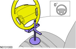
- 1.NOTE: Use a steering wheel holding device (such as Hunter® 28-75-1 or equivalent).
Using a suitable holding device, hold the steering wheel in the straight-ahead position.
- 2.
Remove the wheels and tires. REFER to Wheels and Tires .
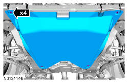
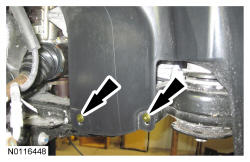
- 5.NOTE: Right Hand(RH) shown in illustration, Left Hand(LH) similar.
Remove the 2 RH and 2 LH lower pin-type retainers from the engine splash shields and position the shields aside.
- 6.
Vehicles equipped with 3.5L GTDI engine, remove the engine exhaust Y-pipe. EXHAUST Y-PIPE -- 3.5L TI-VCT . Vehicles equipped with 3.5L GTDI engine, remove the RH and LH exhaust flexible pipes. EXHAUST FLEXIBLE PIPE -- LH, 3.5L GTDI , or EXHAUST FLEXIBLE PIPE -- RH, 3.5L GTDI .
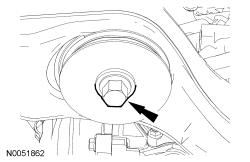
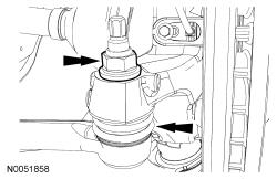
- 8.NOTE: The hex-holding feature can be used to prevent turning of the stud while removing the outer tie-rod end nuts.NOTE: RH shown in illustration, LH similar.
Remove and discard both outer tie-rod end nuts.
- Separate both outer tie-rod ends from the wheel knuckles.
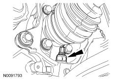
- 9.NOTE: Use care when releasing the lower arm and knuckle into the resting position or damage to the ball joint seal or Constant Velocity(CV) boot may occur.NOTE: Use the hex-holding feature to prevent the stud from turning while removing the lower ball joint nuts.NOTE: RH shown in illustration, LH similar.
Remove and discard both lower ball joint nuts.
- Separate both lower ball joints from the wheel knuckles.
- 10.
If equipped, remove the flap heat shield bolt and position the flap heat shield to access the Electronic Power Assist Steering(EPAS) electrical connectors.
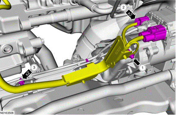
- 11.
- Remove the bolt.
- Disconnect the 2 EPAS electrical connectors.
- Unclip the EPAS harness pushpins and position the harness aside.
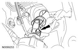
- 12.NOTE: Do not allow the steering column to rotate while the steering column shaft is disconnected from the steering gear or damage to the clockspring may occur. If there is evidence that the steering column has rotated, the clockspring must be removed and recentered. CLOCKSPRING .
Remove and discard the steering column shaft bolt and disconnect the steering column shaft from the steering gear.
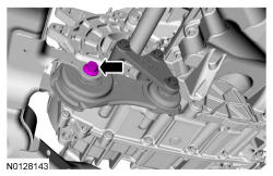
- 13.NOTE: Front Wheel Drive(FWD) shown in illustration, All-Wheel Drive(AWD) Similar.
Remove the rear roll restrictor-to-subframe bolt.
- 15.
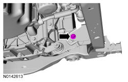
If equipped, unlatch the cooler hose retainer latch. Pry up on the oil cooler hose retainer to release the retainer and remove it from the subframe.
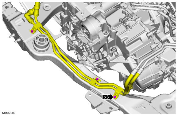
- 17.
Using a wax pencil (or equivalent) apply witness marks to the vehicle and subframe to aid in installation.
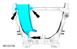
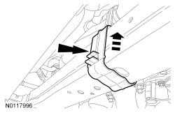
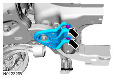
- 19.NOTE: RH shown in illustration, LH similar.
Remove and discard the 4 front subframe bracket bolts.
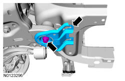
- 20.NOTE: RH shown in illustration, LH similar.
Remove and discard the 2 front subframe rearward bolts and remove the front subframe brackets.
- 21.NOTE: RH shown in illustration, LH similar.
Remove and discard the 2 front subframe forward bolts.