Upper Arm: Installation
- 1.NOTE: Before tightening the shock absorber lower bolts and upper arm nut and bolts, use a jackstand to raise the rear suspension until the distance between the center of the hub and the lip of the fender is equal to the measurement taken in the Removal procedure (curb height).
If removed, install the upper arm bushing onto the upper arm in the following sequence.
- 1.
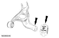
With the upper arm positioned so the top side is facing up and the upper arm bushing is positioned with the TOP OF PART facing up and the ARM TO THIS SIDE arrow is pointing toward the upper arm. Install the upper arm bushing.
- 2.
Install a new upper arm rearward bushing bolt.- Tighten to 200 Nm (148 lb-ft).
- 1.
- 4.
Position the 2 subframe brackets and install 4 new subframe bracket bolts.- Tighten to 55 Nm (41 lb-ft).
- 7.NOTE: Use the hex-holding feature to prevent the stabilizer bar link stud from turning while installing the nut.
Connect the LH and RH stabilizer bar links to the stabilizer bar and install the new nuts.
- Tighten to 55 Nm (41 lb-ft).
- 10.
Position the LH and RH brake caliper and anchor plate assemblies and install the 4 anchor plate bolts.- Tighten to 103 Nm (76 lb-ft).
- 12.
Using the screw-type jackstand, raise the rear suspension until the distance between the center of the hub and the lip of the fender is equal to the measurement taken in the removal procedure (curb height).
- 16.NOTE: A slotted upper arm allows for the rear suspension camber to be adjusted by pushing inward or pulling outward on the wheel knuckle while tightening the upper arm-to-wheel knuckle nut.
With the wheel knuckle pushed inward for maximum negative camber, tighten the upper arm-to-wheel knuckle nut.
- Tighten to 200 Nm (148 lb-ft).
- 18.
Install the rear wheels and tires. REFER to Wheels and Tires
- 19.
Check and, if necessary, adjust the rear camber. REFER to Suspension System - General Information