Instrument Panel Cluster (IPC): Notes
Overview
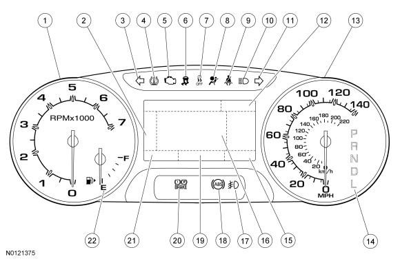
Base IPC
| Item | Description |
|---|---|
| 1 | Tachometer |
| 2 | Main menu navigation |
| 3 | LH turn indicator |
| 4 | TPMS warning indicator |
| 5 | MIL |
| 6 | Stability-traction control indicator (sliding car icon) |
| 7 | Stability-traction control disabled indicator (sliding car OFF icon) |
| 8 | Air bag warning indicator |
| 9 | Safety belt warning indicator |
| 10 | High beam indicator |
| 11 | RH turn indicator |
| 12 | Cruise control indicator display area |
| 13 | Speedometer |
| 14 | PRNDL display (displays PRNDM when equipped with SelectShift) |
| 15 | Odometer display |
| 16 | Message center display area |
| 17 | Fog lamp indicator |
| 18 | ABS warning indicator |
| 19 | Message center rotating indicator display area (also displays outside air temperature when there are no message center warning indicators displayed) |
| 20 | Brake warning indicator |
| 21 | SelectShift display |
| 22 | Fuel gauge |
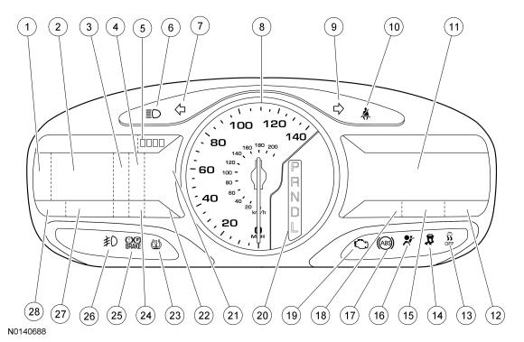
Optional IPC
| Item | Description |
|---|---|
| 1 | Menu navigation icon |
| 2 | LH message center display (displays the 4WD gauge (if equipped) and SelectShift when the tachometer is displayed) |
| 3 | Lane departure warning system display area |
| 4 | Adaptive cruise control display (if equipped) |
| 5 | Submenu display area |
| 6 | High beam indicator |
| 7 | LH turn indicator |
| 8 | Speedometer |
| 9 | RH turn indicator |
| 10 | Safety belt warning indicator |
| 11 | RH multimedia display area |
| 12 | Clock display |
| 13 | Stability-traction control disabled indicator (sliding car OFF icon) |
| 14 | Stability-traction control indicator (sliding car icon) |
| 15 | Compass display |
| 16 | Air bag warning indicator |
| 17 | ABS warning indicator |
| 18 | Outside air temperature display |
| 19 | MIL |
| 20 | PRNDL display (displays PRNDM when equipped with SelectShift) |
| 21 | Gauge display area (fuel, tachometer and temperature based on display settings) |
| 22 | SelectShift display area |
| 23 | TPMS warning indicator |
| 24 | Cruise control message center indicator (fixed indicator display) |
| 25 | Brake warning indicator |
| 26 | Fog lamp indicator |
| 27 | Message center indicator display area (rotating indicator display) |
| 28 | Odometer display |
The base IPC is available with a single LCD screen. The optional IPC is available with dual RH and LH LCD screens. The single display screen and the LH display screen contain the conventional message center information. The RH display screen displays multimedia information (audio, phone and navigation) as well as items such as vehicle direction, outside air temperature and time. For information on the RH display screen, Refer to the appropriate article for the procedure.
Submenu Display Area (Optional IPC Only)
The optional IPC provides an area in the upper RH corner of the LH message center display that is used to indicate the level of submenus that is currently displayed. The number of boxes shown depends on the number of submenu items that are available for selection. The box is filled in (darkened) to indicate the current selection. For example, if there are 4 boxes shown that means that there are 4 submenu items available to select from using the LH steering wheel (message center) right/left button. If the third box is filled in, that means the selected display is the third submenu or 3 button presses to the right.
Informational Indicators/Warning Indicators
Informational indicators provide information to the driver of conditions that exist in the vehicle. Warning indicators provide information to the driver of conditions that could potentially cause personal injury or alter vehicle performance.
Message Center Indicators
Message center indicators illuminate in the message center and replace the typical informational or warning indicator using the same iconic representation. When multiple warnings exist, the message center indicators cycle through each display until the condition has been corrected unless the message center indicator is in a fixed position. The message center indicators include:
- Charging system
- Cruise control (fixed location)
- Door ajar
- Engine oil pressure
- Engine over-temperature
- Grade assist
- Low fuel
- Low washer fluid
- Powertrain malfunction (wrench)
- Tow haul
Network Messaged Inputs
Module messaging has increased over time and become the standard for sending and receiving information required to operate the IPC. The majority of the inputs required to operate the IPC are received over the CAN.
Hardwired Inputs
The IPC requires hardwired inputs from components that are not hardwired to other modules and, therefore, are not on either HS-CAN or the MS-CAN but are required for specific IPC functions or gateway requirements. For additional information about the gateway function, refer to Gateway Function, in this article.
The hardwired inputs are provided by the following components:
- Fuel pump module (primary fuel level input)
- Fuel level sensor (secondary fuel level input)
- Park detect switch (part of the floor shifter assembly)
- Washer fluid level switch
System Operation
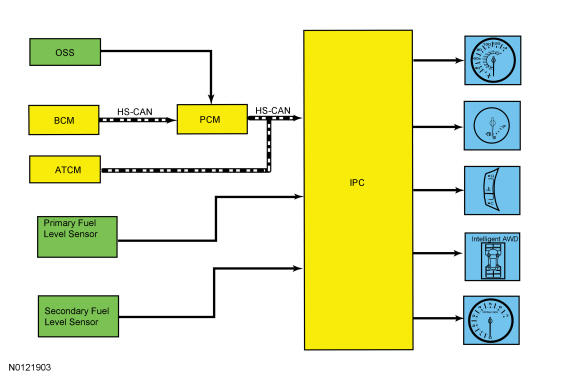
System Diagram - Gauges
Network Message Chart - Gauges
| Broadcast Message | Originating Module | Message Purpose |
|---|---|---|
| AWD lock torque actual | PCM | Input used to generate the 4WD gauge display. |
| Engine coolant temperature | PCM | Engine temperature data used for temperature gauge indication. |
| Engine coolant temperature fault reporting | PCM | Input used to determine the quality of the engine temperature data input for the temperature gauge indication. |
| Engine Revolutions Per Minute (RPM) | PCM | Engine speed data used for tachometer indication and the low oil pressure message center warning indicator. |
| Ignition status | BCM | Ignition RUN, START and accessory states required for the IPC operating modes and fault reporting. |
| Vehicle speed | PCM | Vehicle speed data used for speedometer indication. |
| Vehicle speed fault reporting | PCM | Input used to determines the quality of the vehicle speed data input for the speedometer indication. |
| Wheel torque data | PCM | Provides wheel torque data for the 4WD display. |
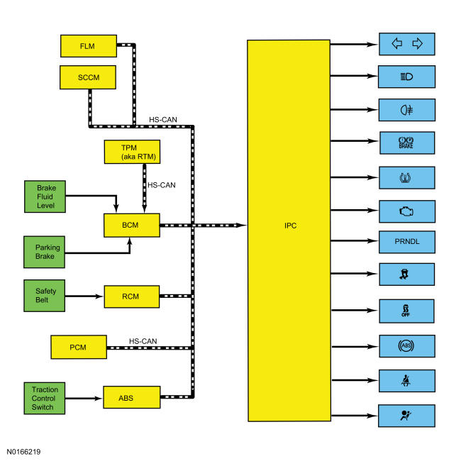
System Diagram - Indicators
Network Message Chart - Indicators
| Broadcast Message | Originating Module | Message Purpose |
|---|---|---|
| Air bag indicator request | RCM | Restraints indicator lamp request used to control the air bag warning indicator. |
| ABS warning indicator request | ABS module | Input required for the ABS warning indicator. |
| Brake warning indicator request | BCM | Input from the BCM required for the brake fluid level and parking brake components of the brake warning indicator operation. |
| Brake (red) warning indicator request | ABS module | Input required from the ABS module for the ABS and EBD components of the brake warning indicator. |
| Engine MIL request | PCM | Input used for the MIL. |
| Fog lamp indicator request | BCM | Input required for the fog lamps indicator. |
| Headlamp high beam indicator request | BCM | Input required for the high beam indicator. |
| Ignition status | BCM | Ignition RUN, START and accessory states required for the IPC operating modes and fault reporting. |
| Safety belt indicator request | RCM | Input used to control the safety belt warning indicator. |
| Selector lever (PRNDL) status | PCM | Transaxle input used for the PRNDL display. |
| Traction control indicator | ABS module | Input required for the stability/traction control indicator (sliding car icon). |
| Traction control disabled (OFF) indicator | ABS module | Input required for the stability/traction control disabled indicator (sliding car OFF icon). |
| Transmission gear display actual | PCM | Transaxle range input used for the PRNDL display. |
| Transmission gear display status | PCM | Transaxle range input used for the PRNDL display. |
| Transmission mode display actual | PCM | Transaxle range input used for the SelectShift display. |
| Transmission mode display status | PCM | Transaxle range input used for the SelectShift display. |
| Transport mode | BCM | Input used to indicate the vehicle is configured in transport mode for the IPC to power down items such as the PRNDL at key off to conserve the battery. |
| Tire pressure warning indicator | BCM | Input required for the IPC to illuminate or flash the TPMS warning indicator. |
| Turn indicator command | BCM | RH and LH turn signal/hazard inputs required for the RH and LH turn/hazard indicator. |
Gateway Function
The IPC acts as a gateway module by receiving information in one format and transmitting it to the audio and multimedia modules using another format. This enables network communication between modules that do not communicate using the same network (Infotainment Controller Area Network (I-CAN) or MS-CAN).
Networked Input Messages and Default States
The IPC uses input messages from other modules to control the gauges, informational indicators, and warning indicators over the communication networks. If a required message is missing or invalid for less than 5 seconds, the gauge or indicator that requires the message remains at the last commanded state based upon the last message received. For example, if the stability/traction control status message is missing for less than 5 seconds and the stability/traction control indicator (sliding car icon) was on, the indicator remains on until the next message is received. If the message remains missing or invalid for more than 5 seconds, the IPC sets a U-code DTC and the IPC output becomes a default action for the indicator or gauge. Each indicator or gauge utilizes a different default strategy depending on the nature of the indication. Refer to the diagnostic overview descriptions located before each individual pinpoint test for further description of the default action specific to each indicator or gauge. If the missing messaged input to the IPC returns at any time, the normal function of the gauge or indicator resumes.
It is very important to understand:
- where the input originates.
- all the information necessary for a feature to operate.
- which module(s) receive(s) the input or command message.
- which module controls the output of the feature.
- whether the module that receives the input controls the output of the feature, or whether it outputs a message over the communication network to another module.
Transport Mode
During vehicle build, some vehicle modules (Instrument Panel Cluster (IPC), BCM and RFR [if equipped]) are set in factory mode. While in the factory mode the IPC displays FACTORY MODE CONTACT DEALER in the message center. If the vehicle is set in factory mode, the system does not automatically revert to another mode and must be manually set to either the transport or normal operation mode. When the vehicle build is complete, the vehicle is set to transport mode. While in transport mode, the IPC displays TRANSPORT MODE CONTACT DEALER in the message center. Transport mode is used to reduce the drain on the battery during longer periods where the vehicle is not used. Various systems may be altered or are disabled when in the transport mode. The vehicle automatically reverts to normal operation mode after being driven.
To disable or turn off the transport mode, carry out (within 10 seconds):
- Verify the battery is fully charged.
- With ignition in RUN, press brake pedal 5 times.
- Press hazard switch 4 times (on, off, on, off).
Startup-Shutdown
The IPC provides a startup/shutdown sequence also known as a welcome/farewell strategy. When the vehicle receives a Remote Keyless Entry (RKE) request or a door ajar (open) message, the IPC gradually increases illumination of the gauge trim rings and turns on the message center (the optional IPC provides a welcome graphic). When the ignition is placed into the RUN or START mode, the IPC begins a prove-out stage. During the prove-out stage, the IPC provides message center information (replaces the welcome screen with vehicle specific information on the optional IPC) while illuminating all LED indicators for a predetermined time. For the shutdown, the IPC reverses the startup process.
MyKey ®
The MyKey ® feature allows the customer to program a restricted driving mode that is tied to one or more keys known as a MyKey ® key. When a MyKey ® programmed key is in use, the IPC provides the following functions:
- At the beginning of vehicle start up, as part of the welcome strategy, the message center greets the MyKey ® driver with MYKEY ACTIVE DRIVE SAFELY displayed in the message center. If the MyKey ® speed limiter feature is turned on, the message center also displays SPEED LIMITED TO XXX KM/H (XX MPH). The MyKey ® top speed selections are: 105, 110, 120 or 130 kmh (65, 70, 75, or 80 mph).
- The IPC continuously provides a periodic Belt-Minder ® warning chime until the driver and passenger safety belts are buckled. When the Belt-Minder ® is issued, the ACM is muted and the message center displays BUCKLE UP TO UNMUTE AUDIO.
- If the MyKey ® speed limiter feature is turned on and the vehicle speed approaches the selected top speed (105, 110, 120 or 130 kmh [65, 70, 75, or 80 mph]), the message center displays VEHICLE NEAR TOP SPEED, along with a chime.
- If the MyKey ® speed limiter feature is turned on and the vehicle speed reaches the selected top speed (105, 110, 120 or 130 kmh [65, 70, 75, or 80 mph]), the message center displays TOP SPEED MYKEY SETTING, along with a chime.
- If the speed warning is selected at one of the preset values (75, 90, 105 km/h [45, 55, 65 mph]) and the vehicle approaches the preset speed, the message center displays CHECK SPEED DRIVE SAFELY along with a chime.
- If the traction control always on feature is turned on and the MyKey ® driver attempts to disable the traction control, the message center displays TRACTION CONTROL SET TO ALWAYS ON.
- At approximately 3/16 tank of remaining fuel, the IPC illuminates the low fuel indicator (if equipped) and the message center displays the appropriate DTE, along with a chime.
- MyKey ® Emergency 911 Assist ® feature and the Do Not Disturb feature can both be found in the MyKey ® menu.
- MyKey ® miles driven by the MyKey ® user can be found in the information display.
- The number of MyKey ® programmed and administrator keys can be found in the information display.
- The parking aid, BLIS ® /CTA and collision avoidance warning menus are disabled in the message center to force these features always on.
When an administrator key is in use, the IPC provides the following functions:
- The message center provides a menu guiding the user to create a MyKey ®. When the maximum MyKey ® limit is reached, the MyKey ® creation menu is no longer available.
- The message center provides menus for setting 4 optional MyKey ® features:
- MyKey ® speed limiter
- MyKey ® pre-selected speed warning
- MyKey ® radio volume limiter
- Traction control on/off
- MyKey ® emergency 911 assist feature
- MyKey ® do not disturb feature
- The message center provides a menu to clear all MyKey ® programmed keys at once.
- MyKey ® mileage driven by the MyKey ® user can be found in system check function of the message center.
- The number of MyKey ® programmed keys and administrator keys can be found in the system check function of the message center.
For additional information on the MyKey ® features, refer to the Owner's Literature.
MyFleet Management (Optional)
The MyFleet management provides an optional police enhanced speed limiting feature that allows the configuration of the maximum vehicle speed. The police enhanced speed limiting feature must be configured using a diagnostic scan tool and can be configured in increments of 8 km/h (5 mph) beginning at 145 km/h (90 mph) up to 8 km/h (5 mph) less than the vehicle's maximum speed.
Configuration
The IPC contains items that are configurable. Configurable items include customer preference items, which can also be set with a scan tool. The remaining configurable items can only be set by the PMI procedure by uploading/downloading existing configuration or by using As-Built data. Refer to the scan tool instructions. The configurable IPC items are:
Configuration - Non-Police Package
| Customer Preference | As-Built Parameter | State Description |
|---|---|---|
| - | 2WD 4WD AWD | 2WD AWD |
| - | ABS | Enabled |
| - | Adaptive cruise control | Disabled |
| - | Adaptive cruise control menu configuration | True False |
| - | Adaptive headlamps | Always |
| - | Advance traction control function | Enabled |
| - | AWD gauge feature | Enabled Disabled |
| - | Auto high beams | Enabled Disabled |
| - | Audio system | DSP present DSP not present |
| - | Autolamp delay | Enabled Disabled |
| - | Autolock control | Enabled |
| - | Auto unlock control | Enabled |
| - | Active park assist | Enabled Disabled |
| Average Fuel Economy (AFE) metric display type | - | Liters-100 kmkm-liter |
| Back up warning chime (Japan only) | - | Enabled Disabled |
| Belt-Minder ® | - | Enabled |
| - | Chime generator | IPC |
| - | Compass | Not present |
| - | Compass Sync | Present Not present |
| Courtesy wipe after wash | - | True |
| - | Cross traffic alert | Enabled Disabled |
| - | Date time strategy | Julian day |
| - | Daytime illumination | Present |
| - | Default language | Refer to the Owner's Literature. |
| - | Do not disturb | Enabled Disabled |
| - | Door content | Doors-liftgate |
| - | Driver alert system | Enabled Disabled |
| - | Easy entry-easy exit | Enabled Disabled |
| - | ESC RSC ® warning chime | Enabled |
| - | Emergency assistance | Enabled Disabled |
| - | EPAS | Enabled |
| - | Flex fuel | No |
| - | Forward collision warning | Enabled Disabled |
| - | Front fog | Enabled Disabled |
| Gallon display type | - | US gallon UK gallon |
| - | Gear select | Select shift Non-select shift |
| - | Global window open | Disabled |
| - | Global window closed | Disabled |
| - | IKT enabled | Enabled Disabled |
| - | Key-in-ignition warning chime | Enabled |
| - | Lane assist | Enabled Full lane departure warning/lane keeping assist |
| - | Lane departure warning off indicator | Disabled |
| - | Multiple chime | Single |
| - | MyKey ® feature supported | Enabled |
| - | MyKey ® speed report | Disabled |
| - | MyKey ® speed limiter | Disabled |
| - | Navigation | Present Not present |
| - | Neutral tow | Disabled |
| - | No gauge sweep-welcome | Enabled |
| - | Number of fuel senders | Two senders |
| - | Number of fuel tanks | One tank |
| - | Oil minder 10K | Enabled |
| - | One/two stage unlocking | Enabled |
| - | Outside air temperature | Enabled Disabled |
| - | Overspeed warning chime | Enabled Disabled |
| - | Park aid front | Disabled |
| - | Park aid rear | Enabled Disabled |
| - | Passive entry/passive start | Enabled Disabled |
| - | Power liftgate control function | Enabled Disabled |
| - | Rain sensing wipers | Enabled Disabled |
| - | Rear fog | Enabled Disabled |
| Rear reverse gear wiper | - | Enabled |
| - | Remote start-climate settings | Enabled Disabled |
| - | Remote start-driver seat | Enabled Disabled |
| - | Remote start-feature | Enabled Disabled |
| - | Remote start-passenger seat | Enabled Disabled |
| - | Remote start-rear defrost | Enabled Disabled |
| - | Remote start-steering wheel | Enabled Disabled |
| - | SDARS | Present Not present |
| - | Side detection | Enabled Disabled |
| - | Speedometer calibration | North America European community countries |
| - | Tank size | 18.6 gallon |
| - | TCM present | Enabled Disabled (Powertrain Control Module (PCM)) |
| - | Terrain management system | Enabled Disabled |
| - | TPMS configuration | Enabled |
| - | Traction control/interactive vehicle dynamics/Roll Stability Control (RSC) | RSC ® |
| - | Trailer sway control | Enabled |
| - | Transmission type | Automatic |
Configuration - Police Package
| Customer Preference | As-Built Parameter | State Description |
|---|---|---|
| - | 2WD 4WD AWD | 2WD AWD |
| - | ABS | Enabled |
| - | Adaptive cruise control | Disabled |
| - | Adaptive headlamps | Always |
| - | AWD gauge feature | Disabled |
| - | Auto high beams | Disabled |
| - | Autolamp delay | Disabled |
| - | Autolock control | Disabled |
| - | Auto unlock control | Disabled |
| - | Active park assist | Disabled |
| - | Advance traction control function | Disabled |
| - | Average Fuel Economy (AFE) metric display type | Liters-100 km |
| Back up warning chime (Japan only) | - | Enabled Disabled |
| Belt-Minder ® | - | Enabled Disabled |
| - | Camera active guide 1 | Enabled Disabled |
| - | Camera-delay | Enabled Disabled |
| - | Camera-parkaid | Enabled Disabled |
| - | Camera-zoom | Enabled Disabled |
| - | Chime generator | IPC |
| - | Continuously controlled dampening (vehicle dynamic suspension) | Disabled |
| Courtesy wipers | - | Enabled |
| - | Cross traffic alert | Enabled Disabled |
| - | Cruise control menu | Disabled |
| Default language | - | English |
| - | DSP present | Not present |
| - | Do not disturb | Disabled |
| - | Doors | Liftgate |
| - | Driver alert system | Disabled |
| - | Easy entry-easy exit | Enabled |
| - | Emergency assistance | Enabled Disabled |
| - | EPAS | Enabled |
| - | Engine hours | Enabled |
| - | Flex fuel | Enabled Disabled |
| - | Forward collision warning | Disabled |
| - | Front fog | Enabled Disabled |
| - | Gallon type | US gallon |
| - | Gear select select shift | Disabled |
| - | GPS based compass | Disabled |
| - | Global window open | Disabled |
| - | Global window closed | Disabled |
| - | Idle hours | Enabled |
| - | Key-in-ignition warning chime | Enabled |
| - | Lane assist | Disabled |
| - | Lane departure warning off indicator | Disabled |
| - | LIN based compass | Disabled |
| - | Multiple chime | Single |
| - | MyKey ® feature | Disabled |
| - | MyKey ® speed limiter | Disabled |
| - | MyKey ® speed volume | Disabled |
| - | Neutral tow | Disabled |
| - | Number of fuel senders | Two senders |
| - | Number of fuel tanks | One tank |
| - | Outside air temperature | Disabled |
| - | Oil minder | Enabled |
| - | Oil pressure input type | Enabled |
| - | Overspeed warning chime | Enabled Disabled |
| - | Park aid-front | Disabled |
| - | Park aid-rear | Enabled Disabled |
| - | Passive entry/passive start | Disabled |
| - | Police auxiliary | Enabled Disabled |
| - | Police enhanced feature speed | Disabled |
| - | Police maximum speed selection | Disabled |
| - | PTY type | RBDS (US) RDS (EU) |
| - | Power liftgate | Disabled |
| - | Rain sensing wipers | Disabled |
| - | Rear camera | Enabled Disabled |
| - | Rear fog | Disabled |
| - | Rear reverse gear wiper | Enabled |
| - | Remote start-climate settings | Enabled Disabled |
| - | Remote start-driver seat | Enabled Disabled |
| - | Remote start-feature | Enabled Disabled |
| - | Remote start-passenger seat | Enabled Disabled |
| - | Remote start-rear defrost | Enabled Disabled |
| - | Remote start-steering wheel | Enabled Disabled |
| - | Right hand screen-climate | Disabled |
| - | Right hand screen-entertainment SIRIUS ® | Disabled |
| - | Right hand screen-entertainment digital audio band (Europe only) | Disabled |
| - | Right hand screen-entertainment compact disc | Disabled |
| - | Right hand screen-navigation | Disabled |
| - | Right hand screen-phone | Disabled |
| - | RSC ® warning chime | Enabled |
| - | SDARS | Present Not present |
| - | Side detection | Enabled Disabled |
| - | Side marker lamp indicator | Disabled |
| - | Speedometer calibration | North America European community countries |
| - | Tank size A | 18.6 gallon |
| - | Tire kit | Disabled |
| - | Transmission type | Automatic |
| - | TPMS | Enabled |
| - | Traction control/interactive vehicle dynamics/Roll Stability Control (RSC) | RSC ® |
| - | Trailer sway control | Enabled |
| - | Transmission type | Automatic |
| - | Turn-by-turn navigation | Disabled |
| - | Two stage unlocking | Enabled |
| - | Welcome and farewell | Disabled |
| - | Welcome ignition behavior | Welcome scene off during crank |
Prove-Out
The IPC and other vehicle modules carry out a display prove-out to verify all module controlled warning/indicator lamps and monitored systems are functioning correctly within the IPC. The IPC and other modules, such as the RCM, provide a timed prove-out while other indicators illuminate until engine start up. When the ignition is cycled to on with the engine off, the indicators illuminate to prove-out according to the following table:
Prove-Out
| Indicator | Indicator Type | Prove-Out Duration |
|---|---|---|
| ABS | Warning | 3 seconds |
| Air bag | Warning | 6 seconds |
| Brake | Warning | 3 seconds |
| Fog lamp | Informational | None |
| High beam | Informational | None |
| MIL | Warning | Engine startup |
| Safety belt | Warning | 70 seconds if the safety belt is unbuckled, turns off when the safety belt is buckled |
| Stability/traction control (sliding car icon) | Warning | 3 seconds |
| Stability/traction control disabled (sliding car OFF icon) | Informational | 3 seconds |
| TPMS | Warning | 3 seconds |
| RH Left Hand (LH) turn | Informational | None |
Dealer Test Mode
To enter the IPC self-diagnostic mode, begin with the ignition in the OFF mode. Press and hold the RH steering wheel switch OK button (optional IPC) or the LH steering wheel switch OK button (base IPC). Place the ignition in the ON mode and hold the button until the display indicates ENGINEERING TEST MODE, usually within 3 to 5 seconds. Press the up or down arrow buttons to navigate through each of the display windows. To exit the IPC self-test mode, press and hold the OK button for 3-5 seconds or place the ignition in the OFF mode. The dealer test mode displays multiple items in a viewing window on the RH side of the IPC. Each button press advances the viewing window to the next set of items.
Dealer Test Mode
| Button Press | Viewing Window Content | Information Display | Description |
|---|---|---|---|
| 1 | Engineering Test Mode | - | Initial entry display into the self-test mode. |
| 2 | Analog Gauge Test | - | Carries out the gauge sweep of analog gauge(s), then displays the present gauge value(s). |
| 3 | Telltale And Color Test | - | Illuminates all the microprocessor controlled indicators and carries out a test of the color bands in the LCD display area. |
| 4 | Part Number Information | PartNo: xxxx-xx Core: xxxx-xx Cal#: xxxx-xx ECU S/W: xxxx-xx | Displays the alphanumeric prefix and suffix of the IPC part number. |
| 5 | Manufacturing Information | Man Date: xx xxxx BA Confg Bytes: xx xx xxxx xx xx xx xx xx xxxx | Displays hexadecimal coding of the final manufacturing test date. |
| 6 | Display all DTC Screen x of x (if more DTCs are set than can be displayed in the viewing window) | DTC HIST CURR xxxxxx x x | Displays DTCs, in hexadecimal format, detected in continuous operation not during self-test. |
| 7 | Gauges Data Filtered | Vehicle Speed x.x km/h x.x MPH Tach xxxx RPM | Displays the filtered English and metric speed value being input in tenths of mph or km/h to the IPC and the filtered Revolutions Per Minute (RPM) data value being input. |
| 8 | Fuel Level (Dual Fuel Sender) | Inst Fuel1: xxx FLPM1: xxxx.x FLPM: xxxx.x | Displays the primary (fuel pump assembly) fuel level. |
| 9 | Fuel Level (Dual Fuel Sender) | Inst Fuel2: xxx FLPM2: xxxx.x FLPM: xxxx.x | Displays the secondary (fuel level sensor) fuel level. |
| 10 | Values used for DTE calculation | DTE: Inst xx Disp km xx xx xx mi xx xx xx | Displays the DTE details. |
| 11 | RAFE RAFE_01 for DTE calculation | RAFERAFE_01 xx.xx.x l/100 km xx.xx.x MPG x.x.x.x km/ 1 | Displays the running Average Fuel Economy (AFE) details. |
| 12 | Fuel Sender 1 (Dual Fuel Senders) | State Val #ofVS Szero: x xx Off: xxx xx On: x xx | Displays the primary (fuel pump assembly) fuel level inputs used to indicate fuel level. |
| 13 | Fuel Sender 2 (Dual Fuel Senders) | State Val #ofVS Szero: x xx Off: xxx xx On: x xx | Displays the secondary (fuel level sensor) fuel level inputs used to indicate fuel level. |
| 14 | Engine Coolant Temperature | Coolant Temp (°C) xx | Displays the last temperature gauge input value from the HS-CAN in degrees C, temperature gauge indicates the present filtered temperature. |
| 15 | Trip Stats A Odo | Odo cnts: xx Trip A: xxx.x km Trip A: xxx.x mi | Displays the trip odometer A values stored in RAM. |
| 16 | Trip Stats B Odo | Odo cnts: xx Trip A: xxx.x km Trip A: xxx.x mi | Displays the trip odometer B values stored in RAM. |
| 17 | Trip Stats A Fuel | Fuel cnts: xxx Fuel A: xx.xx Fuel A: xx.xg | Displays the trip odometer A fuel data stored in RAM. |
| 18 | Trip Stats B Fuel | Fuel cnts: xxx Fuel B: xx.xx Fuel B: xx.xg | Displays the trip odometer B fuel data stored in RAM. |
| 19 | Battery, Compass Last Chime | Battery: xx.x V Compass: xx Last Chime: xx | Displays the current battery voltage input measured on the B+ input. Displays the compass heading input and last chime sounded in hexadecimal format. |
| 20 | Dimming Info Screen 1 | Dim Step: xx Dim Gauge: xxxxx Dim Pointer: xxxxx Dim G. Ring: xxxxx | Displays the IPC dimming levels. |
| 21 | Dimming Info Screen 2 | Dim Step: xx Dim PRNDL: xxxx Dim Display: xxxx | Displays the IPC dimming levels. |
| 22 | Switch Data | PDS: x LWF: x | Displays the park position detect switch and washer fluid level sensor inputs in hexadecimal format. |
| 23 | Engineering Test Mode | - | Repeats the test display cycle. |
Fuel Gauge
The IPC sends a reference voltage to the fuel level sender(s). As the fuel level changes, a float actuates the variable resistor fuel level sender, raising or lowering the fuel level signal voltage. The IPC monitors the changes in voltage from both senders and commands the fuel gauge with a corresponding movement of the pointer.
The IPC interprets both inputs and uses 4 different operating modes to calculate the fuel level:
- Anti-slosh (default mode)
- Key OFF fueling
- Key ON fueling
- Recovery
After a fuel fill up, the time for the fuel gauge to move from empty (E) to full (F) ranges from 2 seconds to 55 minutes depending on which operating mode the fuel gauge is in.
Anti-Slosh Mode
The default fuel gauge mode is called the anti-slosh mode. To prevent fuel gauge changes from fuel slosh (gauge instability due to changes in fuel sensor readings caused by fuel moving around in the tank), the fuel gauge takes approximately 55 minutes to go from empty (E) to full (F).
Key OFF Fueling Mode
The key OFF fueling mode (2 seconds to read empty [E] to full [F]) requires the following conditions be met:
- The ignition must be OFF when refueling the vehicle.
- At least 15% of the vehicle's fuel capacity must be added to the fuel tank.
- The IPC must receive a valid key ON fuel sensor reading within one second of the ignition being put into RUN. The key ON sample readings are considered valid if the fuel sensor reading is between 10 ohms ± 1 ohms and 180 ohms ± 2 ohms.
If these conditions are not met, the fuel gauge stays in the anti-slosh mode, which results in a slow to read full (F) event.
Key ON Fueling Mode
The key ON fueling mode (approximately 60 seconds to read empty [E] to full [F]) requires the following conditions be met:
- The transaxle is in PARK or NEUTRAL.
- The ignition is in RUN.
- At least 15% of the vehicle's fuel capacity must be added to the fuel tank.
In key ON fueling mode, a 30 second timer activates after the transaxle is put into the PARK or NEUTRAL position. When the 30 second time has elapsed and at least 15% of the vehicle's fuel capacity has been added, the fuel gauge response time is 60 seconds to read from empty (E) to full (F). When the transaxle is shifted out of PARK or NEUTRAL, the fuel gauge strategy reverts to the anti-slosh mode. The key ON fueling mode prevents slow to read full events from happening if the customer refuels the vehicle with the ignition in RUN.
Recovery Mode
Recovery mode is incorporated into the IPC strategy to recover from a missing fuel level input after a refueling event. Missing fuel level inputs result from intermittent opens in the fuel sensor or its circuits. Recovery mode (empty [E] to full [F] approximately 20 minutes) is initiated when the following conditions are met:
- The IPC is in the anti-slosh (default) mode.
- The actual fuel level in the tank is greater than what is being displayed by the fuel gauge.
Temperature Gauge
The temperature gauge is located in the LCD display area and is a graphical image as opposed to the more traditionally recognized analog gauge. The base IPC uses a thermometer style image that moves upward as the engine temperature increases, changing color as the temperature reaches predetermined ranges. When the temperature is in the cold band, the thermometer color is blue. When the temperature is in the normal band, the thermometer color is gray and when the temperature is in the hot band, the thermometer color is red.
The optional IPC uses a more traditional gauge image with a single bar set horizontally across the gauge and moves vertically from bottom to top as the engine temperature increases.
The PCM uses the CHT sensor to measure the engine temperature. The IPC uses the engine coolant temperature message from the PCM to control the temperature gauge indication.
Tachometer
The PCM uses the CKP sensor to measure the engine Revolutions Per Minute (RPM). The IPC uses the engine Revolutions Per Minute (RPM) data message from the PCM to control the tachometer.
The base and optional IPC tachometers appear differently but function the same. The base IPC uses an analog gauge. The optional IPC uses a digital display that provides a 6, 000 Revolutions Per Minute (RPM) bar graph or a simulated 7, 000 Revolutions Per Minute (RPM) analog gauge display depending on the selected display mode.
Speedometer
The PCM calculates the vehicle speed from the transaxle OSS sensor input and from the tire size and axle ratio configuration in the PCM VID block. The PCM provides the IPC with a vehicle speed data message to command the speedometer pointer.
The IPC provides a tolerance which allows the gauge to display between 3% lower and 7% higher than the actual vehicle speed. This means that with an actual vehicle speed of 96.6 kmh (60 mph), the speedometer may indicate between 93.7 kmh (58.2 mph) and 103.3 kmh (64.2 mph), which is normal.
Odometer
The IPC receives the odometer count message from the PCM. The IPC monitors the odometer count input from the PCM and commands the odometer with a digital display in the message center.
Brake Warning Indicator
The IPC uses 3 basic messaged inputs to control the brake warning indicator. The first two messages are the parking brake position switch and the brake fluid level switch sent from the BCM. The third is the EBD message sent from the ABS module.
The parking brake position switch is hardwired to the BCM through a single signal circuit while using a separate ground to control the input. The brake fluid level switch is hardwired to the BCM through separate signal and return circuits to control the input.
The BCM provides battery reference voltage to both the parking brake position switch and the brake fluid level switch. When the parking brake is applied, the parking brake position switch closes to ground, pulling the parking brake signal circuit low. When a low brake fluid level condition exists, the brake fluid level switch closes to ground, pulling the signal and return circuits low. If the brake fluid level switch is disconnected, the BCM reference voltage sent to the brake fluid level switch is sent high. When the BCM detects either the brake fluid level signal or the parking brake signal circuits low, or the brake fluid level signal and return circuit high, the BCM sends the IPC a brake warning indicator request.
When the ABS module detects a base brake system concern or other ABS related concerns that affect the EBD function, the ABS module sends a brake (red) warning indicator request to the IPC to illuminate the brake warning indicator and the ABS warning indicator.
ABS Warning Indicator
The IPC uses a ABS warning indicator request from the ABS module to control the ABS warning indicator. If a fault condition exists in the ABS, the ABS module sends the IPC the ABS warning indicator request to either flash or illuminate the ABS warning indicator.
Stability-Traction Control Indicator (Sliding Car Icon)
The IPC uses a traction control indicator request message from the ABS module to control the stability-traction control indicator (sliding car icon). The stability-traction control indicator (sliding car icon) flashes when the vehicle stability-traction control is in active mode or is being controlled by the ABS module. The stability-traction control indicator (sliding car icon) illuminates continuously if a fault condition exists in the stability-traction control system. The IPC monitors the traction control indicator request message from the ABS module and either flashes the stability-traction control indicator (sliding car icon) or illuminates it steady depending on the condition.
Stability-Traction Control Disabled Indicator (Sliding Car OFF Icon)
The stability-traction control is configured on/off through the message center. When the stability-traction control is configured on or off, the IPC sends a message to the ABS module indicating the stability-traction control system has been enabled or disabled by the driver. The ABS module either enables or disables the stability-traction control system and sends a traction control disabled (OFF) indicator request back to the IPC to illuminate or turn off the stability/traction control disabled indicator (sliding car OFF icon) based upon the system state. The stability/traction control system defaults back on or enabled once the ignition is cycled off then back on again.
When a MyKey ® programmed key is in use and the AdvanceTrac ® on feature is configured always on, the traction control system cannot be disabled and the stability-traction control disabled indicator (sliding car OFF icon) does not illuminate when the traction control disable button is pressed. The stability-traction control indicator still functions normally to indicate a stability-traction control system fault and a stability-traction control active event.
LH-RH Turn Signal Indicator
When the multifunction switch is in the LH or RH turn position or if the hazard switch is on, a turn indicator command message is sent to the IPC from the BCM. Upon receipt of the applicable turn signal on/off request, the IPC flashes the turn signal indicator on and off.
High Beam Indicator
When the high beams are turned on, the BCM sends a headlamp high beam indicator request to the IPC to illuminate the high beam indicator.
Fog Lamp Indicator
When the fog lamps are turned on, the BCM sends a fog lamp indicator request to the IPC to illuminate the fog lamp indicator.
Tire Pressure Monitoring System (TPMS) Warning Indicator
The IPC receives the TPMS data from the BCM. The BCM receives the tire pressure status message from the TPM module (also known as the Radio Transceiver Module [RTM]). If the BCM determines the tire pressure has exceeded the low tire pressure limits, a tire pressure status message is sent to the IPC to illuminate the TPMS warning indicator. If a TPMS fault condition exists, the BCM sends the tire pressure status message to the IPC to flash the TPMS warning indicator.
Air Bag Warning Indicator
The IPC receives the air bag warning indicator lamp request from the RCM. If a Supplemental Restraint System (SRS) concern is detected, the RCM sets a DTC and sends an air bag indicator lamp request to the IPC to illuminate the air bag warning indicator.
Safety Belt Warning Indicator
The RCM monitors the safety belt position through the safety belt buckle switch. The RCM sends a safety belt indicator request to the IPC to illuminate the safety belt warning indicator.
Malfunction Indicator Lamp (MIL)
The MIL is controlled by the IPC using an engine MIL request from the PCM.
PRNDL Indicator
The IPC receives the selector lever (PRNDL) status message from the PCM. The IPC also uses a park detect switch (part of the selector lever) input to signal the IPC the shift lever is fully seated in the PARK (P) position. The IPC compares the park detect switch input with the selector lever (PRNDL) status message sent from the PCM. The IPC provides a battery reference voltage to the brake shift interlock. When the selector lever is in PARK (P), the brake shift indicator routes the reference voltage to ground, pulling the circuit low to the IPC. When the selector lever is moved out of PARK (P), the brake shift interlock opens the ground sending the reference voltage high.
The SelectShift display area indicates to the driver which gear is currently selected when the transaxle is in the SelectShift mode. When the transaxle is in SelectShift manual mode, the gear number is displayed in the SelectShift display area.
Terrain Management Indicator
The terrain management warnings inform the driver they have entered or exited one of the various states with respect to the terrain management system. The IPC receives the terrain display request message from the ATCM and displays the terrain management indicator in the 4WD gauge display. The display provides an iconic representation of the selected mode as well as a text-based status message.
Four Wheel Drive (4WD) Gauge
The 4WD gauge displays the level of torque applied to each wheel in a bar graph depicted over the vehicle. The IPC uses 2 inputs to determine the 4WD gauge display. The first is the wheel torque data message sent from the PCM. The second is the 4WD lock torque message also sent from the PCM.
As torque is applied to the wheels, the bars in the display begin to illuminate. The lowest torque displayed is the first bar closest to the wheel. As the amount of torque increases, additional bars are illuminated outward from the wheel.