Pinpoint Test A : System Voltage High
NOTE:
Make sure battery voltage is greater than 12.2 volts prior to and during this pinpoint test.
NOTE:
Do not have a battery charger attached during vehicle testing.
- A1 PERFORM INSPECTION AND VERIFICATION
- Perform the Inspection and Verification .
Was an obvious cause for an observed or reported concern found?
Yes CORRECT conditions as necessary. No GO to A2. - A2 RETRIEVE DTCs
- Using a scan tool, perform PCM self-test.
Is DTC P0620, P0625, P0626 or P065B present?
Yes For DTC P0620, GO to Pinpoint Test C . For DTCs P0625 and P0626, GO to Pinpoint Test D . For DTC P065B, GO to Pinpoint Test E No GO to A3. - A3 MONITOR THE GENERATOR VOLTAGE DESIRED (GENVDSD) PID
- Start the engine.
- Using a scan tool, view the PCM PIDs.
- Monitor the PCM PID GENVDSD.
Does the PID indicate 15.1 volts or less?
Yes GO to A4. No GO to A12. - A4 COMPARE THE GENERATOR VOLTAGE DESIRED (GENVDSD) PID WITH BATTERY VOLTAGE
- With the engine still running at idle, measure and record:
Positive Lead Measurement / Action Negative Lead
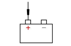
Battery Positive Post
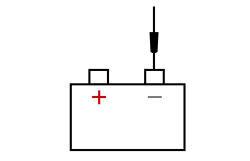
Battery Negative Post
- Using a scan tool, view the PCM PIDs.
- Monitor the PCM PID GENVDSD.
Is battery voltage within ±0.5 volt of the PID ?
Yes The system is operating correctly at this time. The concern may have been caused by a loose or corroded connector. ADDRESS the root cause of any connector or pin issues. No GO to A5. - With the engine still running at idle, measure and record:
- A5 MEASURE THE "A" SENSE VOLTAGE
- Ignition OFF.
- Disconnect: Generator C102A .
- Ignition ON.
- Measure and record:
Positive Lead Measurement / Action Negative Lead
Battery Positive Post
Battery Negative Post
- Measure:
Positive Lead Measurement / Action Negative Lead C102A-3 Ground
Is the "A" sense voltage equal to the recorded battery voltage?
Yes GO to A6. No VERIFY BJB fuse 58 (10A) is OK. If OK, REPAIR the circuit. If not OK, REFER to the SYSTEM WIRING DIAGRAMS article to identify the Possible Sources of the circuit short. - A6 "A" SENSE CIRCUIT LOAD TESTNOTE: The following step uses a test light to simulate normal circuit loads. Use only the test light recommended. To avoid connector terminal damage, use the Flex Probe Kit for the test light probe connection to the vehicle. Do not use the test light probe directly on any connector.NOTE: This step puts a load on the "A" sense circuit. If there are corroded or loose connections, loading the circuit may help show the fault. A 250-350 mA incandescent 12-volt test lamp is required for this step. This circuit cannot be loaded correctly using an LED-style test lamp.
- Ignition OFF.
- Disconnect: Generator C102A .
- Measure battery voltage and record:
Positive Lead Measurement / Action Negative Lead
Battery Positive Post
Battery Negative Post
- Ignition ON.
- Using a 12-volt test lamp connected to ground, while performing a wiggle test on the generator harness, measure voltage at:
Positive Lead Measurement / Action Negative Lead C102A-3 Test Lamp Ground
Is the "A" sense voltage equal to battery voltage?
Yes GO to A7. No REPAIR the circuit. - A7 CHECK THE VOLTAGE DROP IN THE VEHICLE GROUNDS
- Connect: Generator C102A .
- Start the engine.
- With the engine running at idle, headlamps on and blower on high, measure:
Positive Lead Measurement / Action Negative Lead
Generator Case Ground
Battery Negative Post
Is the voltage drop less than 0.5 volt?
Yes GO to A8. No INSPECT and REPAIR the engine ground, generator ground or the battery ground for corrosion. - A8 CHECK THE GENERATOR OUTPUT
- Increase engine Revolutions Per Minute (RPM) until generator starts to generate output.
- With the engine running, measure and record:
Positive Lead Measurement / Action Negative Lead
Battery Positive Post
Battery Negative Post
Is the voltage above 15.2 volts?
Yes INSTALL a new generator. REFER to Generator - 2.0L GTDI or REFER to Generator - 3.5L GTDI or REFER to Generator - 3.5L Ti-VCT . No GO to A9. - A9 MONITOR THE GENERATOR COMMAND (GENCMD), GENERATOR MONITOR (GENMON) AND GENERATOR VOLTAGE DESIRED (GENVDSD) PIDs
- Ignition OFF.
- Disconnect: Generator C102A .
- Start the engine.
- Using a scan tool, view the PCM PIDs.
- Using the active command, set the PID GENVDSD to 14 volts.
- Monitor the PCM PIDs GENMON and GENVDSD.
Do the PIDs read within 5% of each other?
Yes GO to A10. No GO to A12. - A10 COMPARE THE SUPPLY VOLTAGE (VPWR) PID TO BATTERY VOLTAGE
- With the engine still running at idle, measure and record the battery voltage at the battery.
- Monitor the PCM PID VPWR.
Does the PID accurately display battery voltage within ±0.5 volt of the recorded battery voltage?
Yes CHECK OASIS for any applicable TSBs. If a TSB exists for this concern, DISCONTINUE this test and FOLLOW the TSB instructions. If no TSBs address this concern, INSTALL a new generator. REFER to Generator - 2.0L GTDI or REFER to Generator - 3.5L GTDI or REFER to Generator - 3.5L Ti-VCT . No GO to A11. - A11 CHECK PCM SUPPLY VOLTAGE CIRCUITS
- Ignition OFF.
- Remove the fused jumper wire.
- Remove BJB fuse 69 (20A).
- 3.5L Ti-VCT engine, measure:
Positive Lead Measurement / Action Negative Lead
Fuse 69 (15A)C175B-67
Fuse 69 (15A)C175B-68
- 2.0L GTDI engine, measure:
Positive Lead Measurement / Action Negative Lead
Fuse 69 (15A)C1381B-5
Fuse 69 (15A)C1381B-6
- 3.5L GTDI engine, measure:
Positive Lead Measurement / Action Negative Lead
Fuse 69 (15A)C1551B-101
Fuse 69 (15A)C1551B-102
Fuse 69 (15A)C1551B-103
Are the resistances less than 0.5 ohms?
Yes GO to A12. No REPAIR the affected circuit(s). - A12 CHECK FOR CORRECT PCM OPERATION
- Ignition OFF.
- Disconnect and inspect all PCM connectors.
- Repair:
- corrosion (install new connector or terminals - clean module pins)
- damaged or bent pins - install new terminals/pins
- pushed-out pins - install new pins as necessary
- Reinstall BJB fuse 69 (20A).
- Reconnect the PCM and generator connectors. Make sure they seat and latch correctly.
- Operate the system and determine if the concern is still present.
Is the concern still present?
Yes CHECK OASIS for any applicable TSBs. If a TSB exists for this concern, DISCONTINUE this test and FOLLOW the TSB instructions. If no TSBs address this concern, INSTALL a new PCM. REFER to Electronic Engine Controls - 2.0L GTDI or REFER to Electronic Engine Controls - 3.5L GTDI or REFER to Electronic Engine Controls - 3.5L Ti-VCT. No The system is operating correctly at this time. The concern may have been caused by module connections. ADDRESS the root cause of any connector or pin issues.