Tire Pressure Monitoring System: Notes
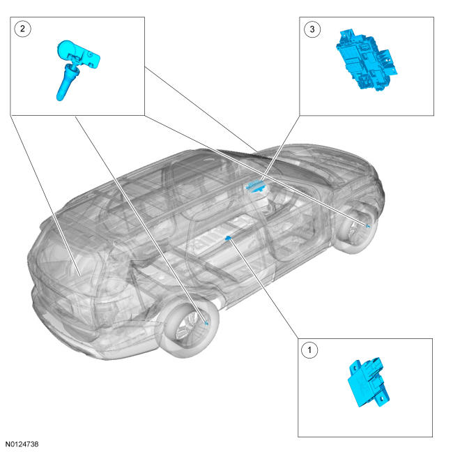
Component Location
TPMS
| Item | Part Number | Description |
|---|---|---|
| 1 | 15K602 | TPM module |
| 2 | 1A189 | TPMS kit assembly (4 required) |
| 3 | - | BCM |
Overview
The BCM monitors the tire pressure in the 4 road tires with tire pressure sensors. The tire pressure sensors are battery operated and mounted to the valve stems. The IPC illuminates the TPMS warning indicator and the message center displays a message when a fault is present or when the tire pressure falls below the low pressure limit.
System Operation
System Diagram
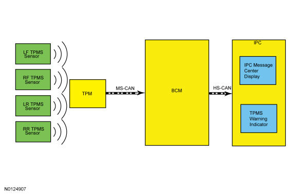
Network Message Chart
| Broadcast Message | Originating Module | Message Purpose |
|---|---|---|
| TPM Module data | TPM Module | Communicates tire pressure information to the BCM |
Tire Pressure Monitoring System (TPMS) Function
The TPMS system monitors the tire pressure using 4 valve stem mounted TPMS sensors to provide accurate tire pressures. Each individual sensor contains its own battery and transmits tire pressure data to the TPM module. The TPM module is a radio receiver that collects the tire pressure data and relays the information via the MS-CAN to the BCM. All of the TPMS functions are controlled by the BCM. The TPMS sensors are trained to the BCM, which records the unique identifier for each TPMS sensor. The BCM records where each TPMS sensor is located based on the training order and compares the actual tire pressure with the desired tire pressure as indicated on the VC label. If the tire pressure deviates from the desired tire pressure the BCM, using the HS-CAN, signals the IPC to illuminate the TPMS warning indicator and also displays a message on the message center. The programmed tire pressure cannot be changed.
The scan tool is a useful tool in diagnosing TPMS concerns and may be used to verify if the TPMS sensors are transmitting accurate tire pressure data by comparing the PID tire pressure data in the BCM to the actual tire pressure using a digital tire pressure gauge. Training the sensors is not necessary after a tire rotation on vehicles with the same front and rear tire pressures, but the BCM cannot recognize that the sensor identifiers have been moved to different positions, it only retains the original position the sensors were last trained to.
Wheel Rotation and Sensor Training Techniques
Training known good sensors from another vehicle cannot differentiate between a faulted module and RFI, as some noise source could be preventing the TPM module from receiving the tire pressure status from the original sensors as well as the known good sensors. This technique can be used to differentiate between a sensor and module issue. If the TPM module in the vehicle cannot train any of the sensors on the same vehicle, and likewise cannot train known good sensors from another vehicle, then the issue is with the module or RFI and not with the original sensors. The original sensors should not be replaced. If a sensor in a certain location has caused several events, yet the sensor trains and seems to operate normally, moving that particular wheel to a different location on the vehicle is a good way to isolate the issue to a certain sensor/wheel location. Rotate the wheels and road test the vehicle. This can be done in an attempt to replicate the issue and help determine if the issue followed the sensor or remained in the original sensor location. If the vehicle has been stationary for more than 30 minutes, the sensors go into a "sleep mode" to conserve battery power. It becomes necessary to wake them up so they transmit the latest tire pressure information to the TPM module. Refer to Tire Pressure Monitoring System (TPMS) Sensor Activation .
Training Sensors in a Different Order
If the first sensor fails the TPMS training procedure, the BCM aborts the entire procedure. Starting the training procedure at a different wheel is a technique that can be used to determine if the remaining sensors can train to the module. This can help save time determining if one sensor is damaged, other sensors are having issues, or the BCM is experiencing training difficulties with a certain TPMS sensor location.
Tire Pressure Monitoring System (TPMS) Indicator
The TPMS indicator and vehicle message center sometimes display faults that cannot be resolved by the customer. Treat these messages as TPMS faults that must be serviced.
TPMS Warning Indicator Illuminates Continuously
The TPMS warning indicator remains on continuously and the message center displays LOW TIRE PRESSURE when any of the tire pressures fall below the low pressure limit. When this condition exists, adjust the tire pressure to the recommended cold tire pressure indicated on the VC label.
TPMS Warning Indicator Flashes
The TPMS warning indicator flashes for 70 seconds, then remains on continuously when the ignition is turned to the ON position when the TPMS is malfunctioning. The PID TP_STAT can be used to determine why the TPMS warning indicator is flashing.
- Tire Pressure Sensor Fault - The message center displays TIRE PRESSURE SENSOR FAULT when a TPMS sensor is malfunctioning. Refer to Tire Pressure Monitoring System .
- No communication with the BCM - The TPMS warning indicator illuminates when the IPC has not received any signals from the BCM for more than 5 seconds. The message center displays TIRE PRESSURE MONITOR FAULT. Refer to Tire Pressure Monitoring System .
- Tire Pressure Monitor Fault - The message center displays TIRE PRESSURE MONITOR FAULT when the TPMS is malfunctioning. Refer to Tire Pressure Monitoring System .
Tire Pressure Monitoring System (TPMS) PID Definitions
The BCM monitors the TPMS status. The current status can be viewed by accessing the TPMS status PID : TPMS_STAT using the scan tool. This helps identify the current system status and may aid in diagnosing the system. The PID has 4 valid states:
- TPMS_STAT = SENSOR FAULT If the BCM has not received the tire pressure data from 1 to 3 TPMS sensors for 20 minutes when the vehicle speed is above 32.2 kmh (20 mph), the PID displays SENSOR FAULT.
- TPMS_STAT = SYSTEM FAULT If the BCM has not received the tire pressure data from all 4 sensors for 20 minutes when the vehicle speed is above 32.2 kmh (20 mph), the PID displays SYSTEM FAULT.
- TPMS_STAT = LOW If the BCM has detected that at least 1 TPMS sensor is reporting low tire pressure, the PID displays LOW.
- TPMS_STAT = ACTIVE If the TPMS is functioning normally, the PID displays ACTIVE.
Last Warning Event PID Definitions
The TPMS uses the TPMS last warning event PIDs to store detailed information about the last 5 times the TPMS warning indicator was activated. These PIDs can be used to acquire more information about a particular TPMS event, but must be used carefully.
| EVT1_AGE_IGN through EVT5_AGE_IGN | The number of key cycles since the TPMS was activated. This PID cycles from zero to 255 and then starts over from zero again. Default is $00, this can be used to determine how long ago a TPMS event occurred and the time (in key cycles) between events. |
|---|---|
| EVT1_TR_LOC through EVT5_TR_LOC | This is the last programmed location for the TPMS sensor identifier causing each TPMS event. Due to tire rotation, the sensor may no longer be at the original location. It is suggested that all the PIDs be recorded, the system retrained, and then the sensor identifier PIDs be used to pinpoint the actual location of each sensor. |
| EVT1_PSI through EVT5_PSI | This is the tire pressure associated with each TPMS indicator event. This can be used along with the function code to clearly identify the TPMS events that were strictly due to low pressure. It can also be used to determine when a sensor is transmitting inaccurate tire pressure. |
| EVT1_SNSR_ST through EVT5_SNSR_ST | UNKNOWN NORMAL (normal operation) LOW (low pressure event) FAULT (sensor fault or system fault) |
| EVT1_SNSR_ID through EVT5_SNSR_ID | This is the identifier of the sensor involved in each TPMS event. EVT1 is the most recent event that triggered the TPMS warning indicator. Default is $ 00 00 00 00. |
Radio Frequency Interference
The following equipment has been found to cause RFI :
- Video equipment has been found to cause RFI especially when the video and power supply lines are near the TPMS.
- Car alarms (even those installed by the dealership) have been found to create enough RFI to cause the TPMS to malfunction or lose considerable range. These car alarms can be difficult to locate, as they are usually hidden somewhere out of the way for reduced accessibility.
- Many in-vehicle cell phone chargers have been found to cause considerable RFI. The vehicles with the power point closest to the TPM module are the most affected. It must be noted that most cell phone chargers do not produce high levels of RFI all the time. This depends on the state of charge of the cell phone battery. The phone battery must be almost completely discharged in some cases.
- Power supplies and DC /AC inverters typically create a lot of RFI. Most consumer grade equipment has very little filtering or shielding.
OEM Modules
In some cases the RFI may actually be caused by a module or ground on the vehicle. Depending on the severity of the issue, a dirty ground, improperly built ground shield or module can disable the system. Modules that have microcontrollers using clock circuits to create timing pulses for the microprocessor may radiate RFI.
Using Customer's Electronics to Pinpoint Radio Frequency Interference
This method can be a way to determine the cause of an issue well before the sensors and module are replaced with little or no effect on the system performance. Since this takes more up front work, it relies on working with the customer to determine what equipment was being used at the time of the event. Question the customer about what kind of devices they are using. Determine which power points are being used and if necessary ask that the devices be activated to determine their affect on the TPMS.
Options for Eliminating Intermittent TPMS Operation Caused by RFI
- If an OEM component or customer device is causing an RFI issue, replace the device.
- If a phone charger is causing an RFI issue, the customer should consult with their cell phone provider to acquire a different battery charger.
- If a device such as a dealer installed alarm is causing an RFI issue, move the device to another location in the vehicle. In the case of a portable device move the power cord to another power point location.
In summary, if the RFI source is present and cannot be moved or replaced, the intermittent issue remains. The TPMS must accept the unwanted system operation it can cause.
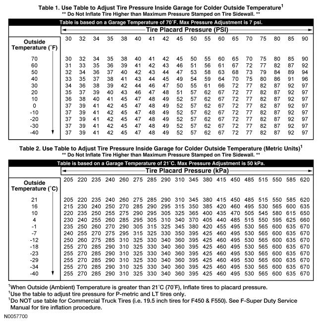
Ambient Temperature Change and Tire Pressure
Tire pressures fluctuate with temperature changes. For this reason, tire pressures must be set to specification when tires are at outdoor ambient temperatures. If the vehicle is allowed to warm up to shop temperatures, and the outside temperature is less than shop temperature, the tire inflation pressure must be adjusted accordingly.
If the tires are inflated to specification at shop temperatures, and the vehicle is moved outdoors when the outdoor ambient temperature is significantly lower, the tire pressure may drop enough to be detected by the TPMS and activate the TPMS warning indicator.
As the ambient temperature decreases by -12.2°C (10°F) tire pressure decreases 6.9 kPa (1 psi). Adjust the tire pressure by 6.9 kPa (1 psi) for each -12.2°C (10°F) ambient temperature drop as necessary to keep the tire at the specified VC label pressure. To adjust the tire pressure indoors for colder outside temperatures: