Component Description
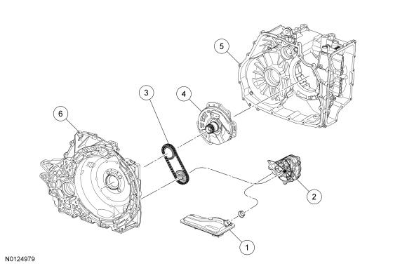
Transmission Pump and Fluid Filter
The transmission fluid in the sump area at the bottom of the transmission case flows through a transmission fluid filter to the pump assembly. The pump is bolted to the torque converter housing and is chain driven from a sprocket that is mounted on the stator support and turned by the torque converter.
| Item | Description |
|---|---|
| 1 | Transmission fluid filter assembly |
| 2 | Pump assembly |
| 3 | Chain and sprocket assembly |
| 4 | Stator support assembly |
| 5 | Transmission case |
| 6 | Torque converter housing |
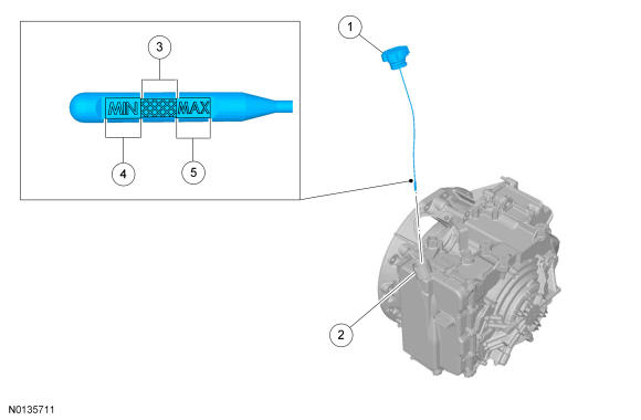
Transmission Fluid Level
The transmission fluid level is checked with the transmission at normal operating temperature between 82.3 °C (180 °F) and 93.4 °C (200 °F). The transmission fluid level indicator is part of the filler cap. The correct transmission fluid level is between the MIN and MAX in the cross hatches of the transmission fluid level indicator.
| Item | Description |
|---|---|
| 1 | Transmission fluid level indicator |
| 2 | Main control cover assembly |
| 3 | Correct transmission fluid level at normal operating temperature |
| 4 | Low transmission fluid level at normal operating temperature |
| 5 | High transmission fluid level at normal operating temperature |
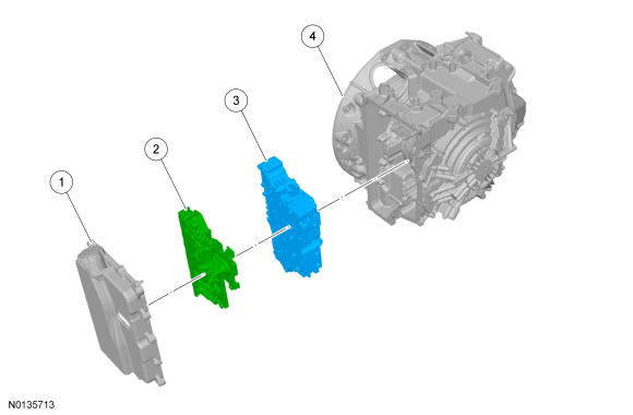
Main Control
The hydraulic system has a main control assembly. The main control assembly consists of a valve body and a solenoid body. The valve body contains the hydraulic regulator and multiplex shift valves. The solenoid body contains the shift solenoids that control the hydraulic valves. The solenoid body is serviced as an assembly and can not be disassembled. The solenoid body is controlled by the PCM. The PCM has software stored in it specific to the solenoid body currently in the transmission, called the solenoid body strategy. A new solenoid body strategy must be downloaded into the PCM any time a new solenoid body is installed.
| Item | Description |
|---|---|
| 1 | Main control cover assembly |
| 2 | Solenoid body |
| 3 | Main control valve body |
| 4 | Transmission case |
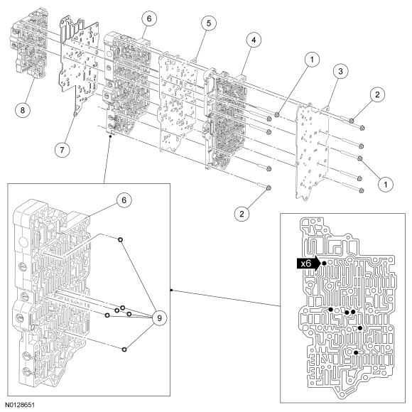
| Item | Description |
|---|---|
| 1 | Bolts -M6 x 63 |
| 2 | Bolts - M6 x 35 |
| 3 | Cover - transfer plate |
| 4 | Case-to-valve body transfer plate |
| 5 | Separator plate - valve body-to-transfer plate |
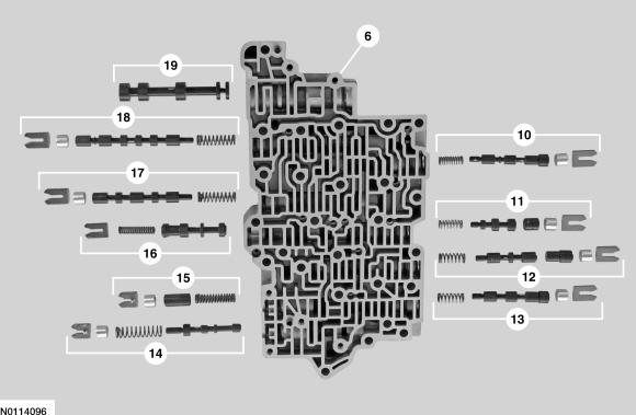
| 6 | Main control valve body |
| 7 | Separator plate - main control valve body-to-lower valve body |
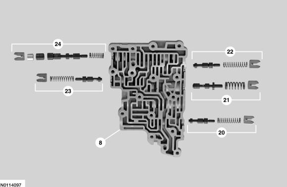
| 8 | Lower valve body assembly |
| 9 | Check balls |
| 10 | Low/reverse and overdrive clutch regulator valve assembly |
| 11 | Torque converter clutch regulator apply valve assembly |
| 12 | Intermediate clutch regulator valve assembly |
| 13 | Direct clutch regulator valve assembly |
| 14 | Pressure regulator valve assembly |
| 15 | Isolator valve assembly |
| 16 | Torque converter clutch control valve assembly |
| 17 | Multiplex manual valve |
| 18 | Multiplex shift valve |
| 19 | Manual valve |
| 20 | Direct clutch boost valve assembly |
| 21 | Solenoid regulator valve assembly |
| 22 | Low/reverse and overdrive clutch boost valve assembly |
| 23 | Forward clutch boost valve assembly |
| 24 | Forward clutch regulator valve assembly |
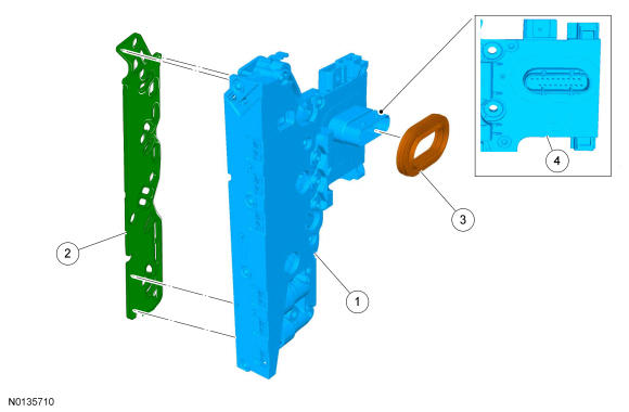
| Item | Description |
|---|---|
| 1 | Solenoid body |
| 2 | Solenoid body filter |
| 3 | Seal - solenoid body electrical connector |
| 4 | Leadframe area |
Multi-Plate Clutch
Multi-plate clutches are clutches that consist of multiple friction and steel clutch discs that when pressure is applied, either drive or hold (brake) components of the planetary gearset. This transmission has 5 multi-plate clutches:
- Forward (1, 2, 3, 4)
- Direct (3, 5, R)
- Intermediate (2, 6)
- Overdrive (4, 5, 6)
- Low/reverse
Both the direct (3, 5, R) and the overdrive (4, 5, 6) clutches are drive clutches. The direct (3, 5, R) clutch drives the rear planetary sun gear and the overdrive (4, 5, 6) clutch drives the rear planetary carrier. The forward (1, 2, 3, 4), intermediate (2, 6) and the low/reverse clutches are brake clutches. The forward (1, 2, 3, 4) clutch holds the front sun gear, the intermediate (2, 6) clutch holds the rear sun gear and the low/reverse clutch holds the rear planetary carrier.
Clutches; overdrive (4, 5, 6) and direct (3, 5, R) are balanced in terms of dynamic pressure. That is, their pistons are exposed to the transmission fluid flow on both sides to prevent pressure buildup in the clutch as speed increases. This dynamic pressure equalization process is achieved by a baffle plate and pressure-free transmission fluid supply by a lubricating passage, through which the space between the piston and baffle plate is filled with transmission fluid.
The advantages of this dynamic pressure equalization are:
- reliable clutch engagement and release in all speed ranges.
- improved shift refinement.
External Sealing
The torque converter housing has a lip-type seal that seals the torque converter hub. The manual control lever shaft and half shafts also use lip-type seals. AWD vehicles do not use a RH half shaft seal, the transmission is sealed by the PTU on the RH side.
The torque converter housing is sealed to the transmission case with silicone sealant.
The transmission cover is sealed to the transmission case with a reusable gasket. The main control cover is sealed to the transmission case and the solenoid body with reusable rubber gaskets.
The TSS sensor is sealed to the transmission cover with an O-ring seal. The transmission fluid filler tube is sealed to the main control cover with an O-ring seal that is serviced with the transmission fluid filler tube. The transmission fluid level indicator is sealed to the transmission fluid filler tube with an O-ring seal that is serviced with the transmission fluid level indicator.
The line pressure tap plug, transmission fluid drain plug and the lubrication circuit tap plug have pipe threads and seal when tightened to specification.
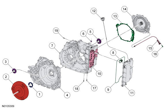
| Item | Description |
|---|---|
| 1 | Torque converter hub seal |
| 2 | Torque converter |
| 3 | RH halfshaft seal (FWD only) |
| 4 | Torque converter housing |
| 5 | LH halfshaft seal |
| 6 | Manual control lever shaft seal |
| 7 | Transmission case |
| 8 | Main control cover-to-solenoid body seal |
| 9 | Main control cover gasket |
| 10 | Solenoid body assembly |
| 11 | Main control cover |
| 12 | Transmission fluid level indicator |
| 13 | Transmission case-to-transmission cover gasket |
| 14 | Transmission cover |
| 15 | TSS sensor |
| 16 | TSS sensor bolt |
| 17 | Line pressure tap plug |
| 18 | Transmission fluid drain plug |
| 19 | Lubrication circuit tap plug |
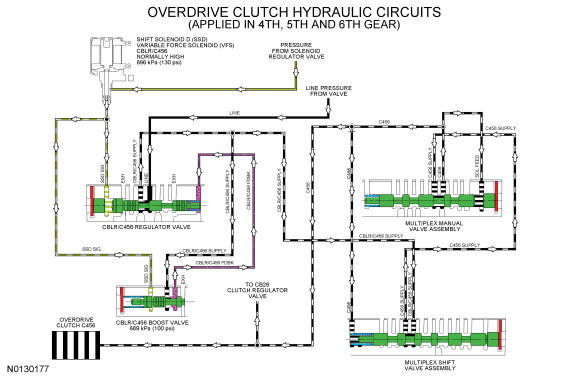
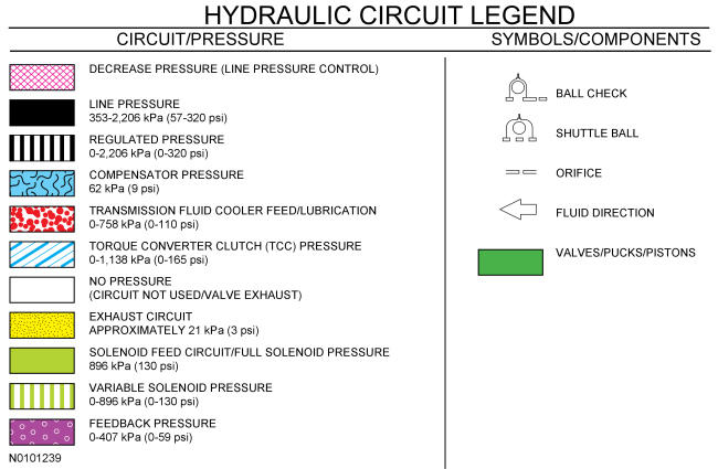
Hydraulic Circuits Legend
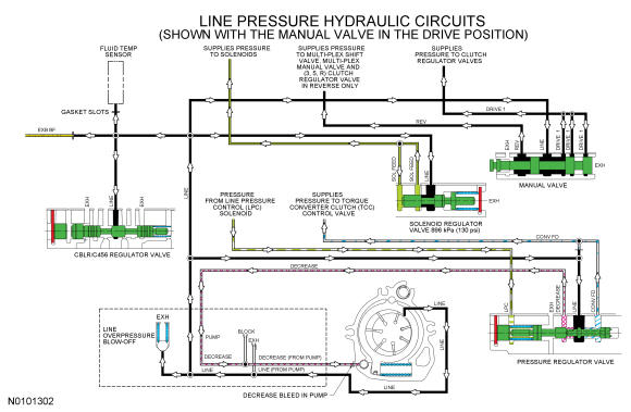
Line Pressure Hydraulic Circuits
The PCM controls line pressure with the LPC solenoid. This affects shift feel and apply component operation.
When the engine is running, the pump supplies pressure to the pressure regulator valve, which is controlled by the LPC solenoid. The pressure regulator valve controls the line pressure.
The line pressure circuit supplies the manual valve. The manual valve directs the line pressure to either the REV/REV SUPPLY circuit when the manual control lever is in the REVERSE position or the DRIVE 1 circuit when the manual control lever is in the DRIVE or LOW position.
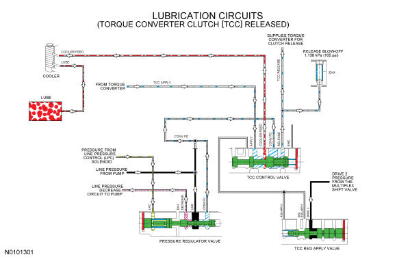
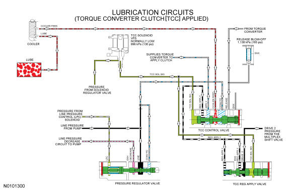
Lubrication Hydraulic Circuits
Lubrication for the transmission is supplied by the transmission fluid cooler return tube. Transmission fluid is sent to the transmission fluid cooler from the TCC control valve.
LINE pressure supplied to the pressure regulator valve is sent to the TCC control valve as CONV FD pressure. During TCC release, the TCC control valve sends the transmission fluid to the torque converter to release the clutch. The transmission fluid returns to the TCC control valve from the torque converter and is directed to the transmission fluid cooler on the COOLER FEED circuit.
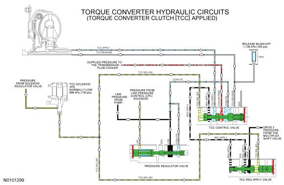
Torque Converter Hydraulic Circuits
The PCM controls the TCC solenoid. The TCC solenoid applies hydraulic pressure to the TCC control and regulator apply valves through the TCC SOL SIG circuit. Regulated DRIVE 2 pressure from the multiplex shift valve is directed to the TCC control valve by the TCC regulator apply valve through the REG APPLY circuit. The TCC control valve directs pressure from the REG APPLY circuit to the TCC APPLY circuit to apply the clutch.
The transmission fluid returns to the TCC control valve through the TCC RELEASE hydraulic circuit. The TCC control valve opens the TCC RELEASE circuit to exhaust, so the TCC RELEASE circuit is not pressurized when the TCC is applied.
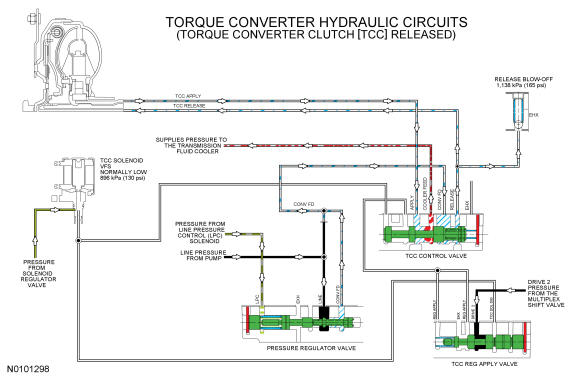
When the TCC is released, The TCC solenoid does not apply hydraulic pressure to the TCC control or regulator apply valves. The TCC control valve, in this position, directs hydraulic pressure from the CONV FD circuit to the torque converter through the TCC RELEASE hydraulic circuit and it returns to the TCC control valve through the TCC APPLY circuit.
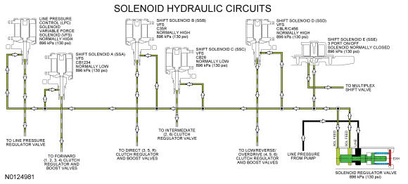
Solenoid Hydraulic Circuits
LINE pressure from the pump is directed to the individual shift, TCC and LPC solenoids by the solenoid regulator valve on the SOL FEED circuit. The solenoids, controlled by the PCM, direct the fluid to the valves that they control.
The LPC solenoid sends varying pressure to the line pressure regulator valve to control line pressure.
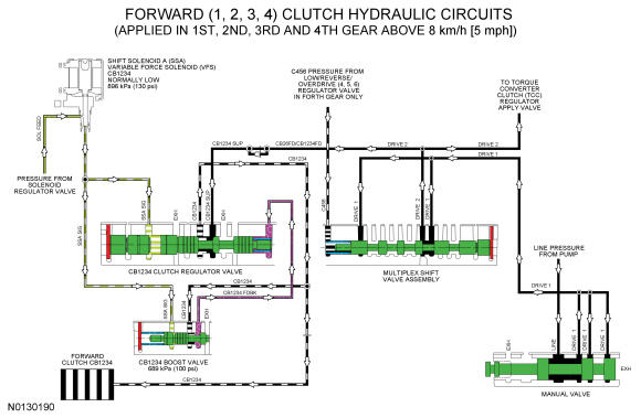
Forward Clutch Hydraulic Circuits
When the forward (1, 2, 3, 4) clutch is applied in 1st (above 8 kmh (5 mph), 2nd, 3rd and 4th gears, LINE pressure from the pump is directed to the multiplex shift valve by the manual valve through the DRIVE 1 hydraulic circuit. The multiplex shift valve supplies the forward (1, 2, 3, 4) clutch regulator valve with pressure through the DRIVE 2, CB26FD/CB1234FD and CB1234 SUP hydraulic circuits. The forward (1, 2, 3, 4) clutch regulator valve directs regulated pressure to the forward (1, 2, 3, 4) clutch through the CB1234 hydraulic circuit
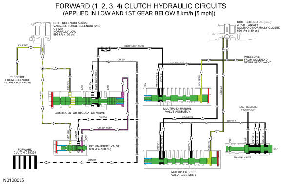
When the forward (1, 2, 3, 4) clutch is applied in LOW position and 1st gear below 8 kmh (5 mph), LINE pressure from the pump is directed to the multiplex shift valve by the manual valve through the DRIVE 1 hydraulic circuit. The multiplex shift valve directs the pressure to the multiplex manual valve through the REV DRIVE B circuit. The multiplex manual valve directs the REV DRIVE B pressure to the forward (1, 2, 3, 4) clutch regulator valve through the DRIVE B, CB26FD/CB1234FD and CB1234 SUP circuits. SSA supplies varying solenoid pressure to the CB1234 clutch regulator and boost valves. As the CB1234 clutch regulator valve moves, it supplies the forward (1, 2, 3, 4) clutch and CB1234 boost valve with regulated line pressure through the CB1234 circuit. The CB1234 boost valve directs the regulated line pressure to the opposite side of the regulator valve through the CB1234 FDBK circuit for controlled forward (1, 2, 3, 4) clutch engagement.
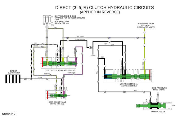
Direct (3, 5, R) Clutch Hydraulic Circuits
When the direct (3, 5, R) clutch is applied in REVERSE, LINE pressure from the pump is directed to the multiplex manual valve by the manual valve through the REV hydraulic circuit. The multiplex manual valve supplies the direct (3, 5, R) clutch regulator valve with pressure through the REV SUPPLY and C35R SUPPLY hydraulic circuits. To apply the direct (3, 5, R) clutch, SSB applies varying solenoid pressure to the C35R clutch regulator and boost valves. As the C35R regulator valve moves, it supplies the direct (3, 5, R) clutch and C35R boost valve with regulated line pressure through the C35R circuit. The C35R boost valve directs the regulated line pressure to the opposite side of the C35R clutch regulator valve through the C35R FDBK circuit for controlled direct (3, 5, R) clutch engagement.
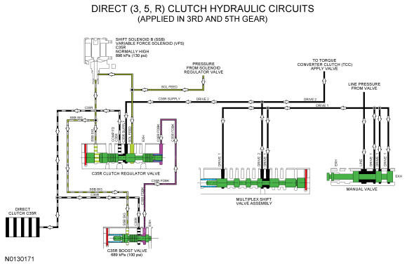
When the direct (3, 5, R) clutch is applied in 3rd and 5th gears, LINE pressure from the pump is directed to the multiplex shift valve by the manual valve through the DRIVE 1 hydraulic circuit. The multiplex shift valve directs the pressure to the direct (3, 5, R) clutch regulator valve through the DRIVE 2/C35R SUPPLY circuits. To apply the direct (3, 5, R) clutch, SSB applies varying solenoid pressure to the C35R clutch regulator and boost valves. As the C35R regulator valve moves, it supplies the direct (3, 5, R) clutch and C35R boost valve with regulated line pressure through the C35R circuit. The C35R boost valve directs the regulated line pressure to the opposite side of the C35R clutch regulator valve through the C35R FDBK circuit for gradual direct (3, 5, R) clutch engagement.
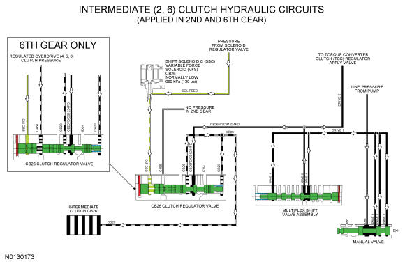
Intermediate (2, 6) Clutch Hydraulic Circuits
When the intermediate (2, 6) clutch is applied in 2nd and 6th gears, LINE pressure from the pump is directed to the multiplex shift valve by the manual valve through the DRIVE 1 hydraulic circuit. The multiplex shift valve supplies the intermediate (2, 6) clutch regulator valve with pressure through the DRIVE 2 and CB26FD/CB1234FD hydraulic circuits. The intermediate (2, 6) clutch regulator valve is controlled by SSC and directs regulated pressure to the intermediate (2, 6) clutch through the CB26 hydraulic circuit. The CB26 hydraulic circuit also supplies pressure to the opposite side of the CB26 clutch regulator valve for controlled intermediate (2, 6) clutch engagement. Regulated overdrive (4, 5, 6) clutch pressure is supplied to the intermediate (2, 6) clutch regulator valve in 6th gear to boost the SSC solenoid pressure.
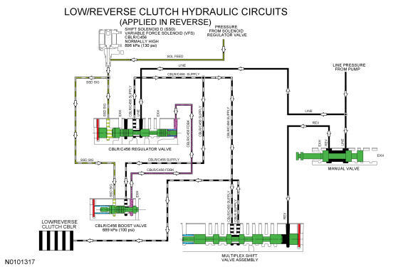
Low-Reverse Clutch Hydraulic Circuits
When the low-reverse clutch is applied in REVERSE, LINE pressure from the pump is directed to the multiplex shift valve by the manual valve through the REV hydraulic circuit to move the valve. Line pressure is also supplied to the low-reverse/overdrive clutch regulator valve from the pump. The low-reverse/overdrive clutch regulator valve is controlled by SSD and directs regulated pressure to the multiplex shift valve. The multiplex shift valve directs the regulated pressure to the low-reverse clutch through the CBLR SUPPLY circuit.
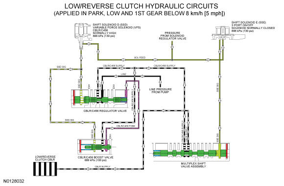
When the low-reverse clutch is applied in PARK, LOW or 1st gear below 8 kmh (5 mph), SSE pressure is supplied to the multiplex shift valve to move the valve. LINE pressure is supplied to the low-reverse/overdrive clutch regulator valve from the pump. The low-reverse/overdrive clutch regulator valve is controlled by SSD and directs regulated pressure to the multiplex shift valve. The multiplex shift valve directs the regulated pressure to the low-reverse clutch through the CBLR SUPPLY circuit.
Overdrive Clutch Hydraulic Circuits
When the overdrive clutch is applied in 4th, 5th and 6th gears, LINE pressure is supplied to the low-reverse/overdrive (4, 5, 6) clutch regulator valve from the pump. To apply the overdrive (4, 5, 6) clutch, SSD applies varying solenoid pressure to the CBLR/C456 regulator and boost valves. As the CBLR/C456 regulator valve moves, it supplies the multiplex shift valve assembly and CBLR/C456 boost valve with regulated line pressure through the CBLR/C456 SUPPLY circuit. The CBLR/C456 boost valve directs the regulated line pressure to the opposite side of the CBLR/C456 regulator valve through the CBLR/C456 FDBK circuit for controlled overdrive (4, 5, 6) clutch engagement. The multiplex shift valve directs the regulated pressure to the multiplex manual valve through the C456 SUPPLY hydraulic circuit. The multiplex manual valve directs the regulated pressure to the overdrive (4, 5, 6) clutch through the C456 hydraulic circuit. The C456 circuit also supplies pressure to the CB26 clutch regulator valve to boost the pressure from SSC in 6th gear.