Main Control Valve Body: Installation
- 1.
- 1.
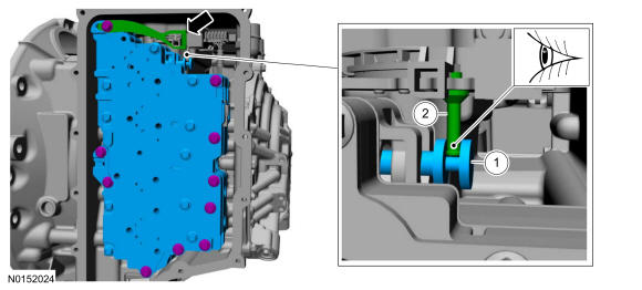
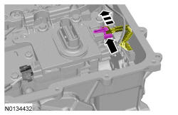
Manual valve.
- 2.
Manual pin.
- 1.
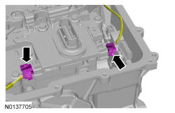
NOTE:
Make sure that the manual control lever pin (part of the TR sensor) is correctly installed in the manual control valve.
NOTE:
If cleaning of the main control assembly or inspecting the valves, refer to Main Control - Overhaul . If installing a new main control assembly continue with this procedure.
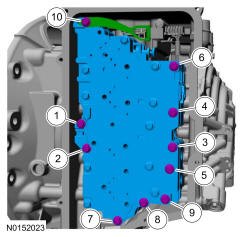
NOTE:
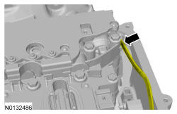
Be careful not to pinch the TSS, OSS or TR sensor wiring harnesses under the valve body, or damage to the wiring harness or connectors may occur.
- 3.
Hand-tighten only.- 1.
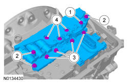
42 mm (1.653 in) bolt
- 2.
63 mm (2.48 in) bolts
- 3.
80 mm (3.149 in) bolts
- 4.
95 mm (3.74 in) bolts
- 1.
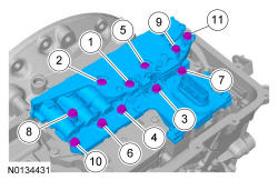
NOTE:
Make sure not to pinch the TSS, OSS or TR sensor wiring harnesses when positioning the solenoid body in place.
- 8.
Install the main control cover. For 3.5L GTDI refer to, Main Control Cover - 3.5L GTDI . For 3.5L Ti-VCT refer to, Main Control Cover - 3.5L Ti-VCT .
- 9.
If a new solenoid body is installed, the PCM will must be reflashed with a new solenoid body strategy and identification data file. Refer to Solenoid Body Strategy Download .