Transmission - 3.5L GTDI: Installation
NOTE:
Prior to installation of a new, re-manufactured or overhauled transmission, the transmission fluid cooler tubes must be cleaned, otherwise transmission failure may occur.
NOTE:
Prior to installation of a new, re-manufactured or overhauled transmission, flush out the cooler and cooler tubes. REFER to Transaxle Transmission Cooling
.
- 4.
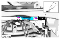
- Tighten to 18 Nm (159 lb-in).
NOTE:
Make sure to hold the manual control lever while tightening the manual control lever nut or damage to the manual control lever and park components will occur.
NOTE:
Make sure that when installing the manual control lever, it is fully seated onto the manual control lever shaft. Damage to the manual control lever shaft will occur and the manual lever will come loose.
- 6.
NOTE:
If the dowel pins were pulled out of the engine block during removal, install new dowel pins in the engine block.
NOTE:
If the transmission is not positioned on the dowel pins, damage to the transmission may occur.
- 8.
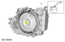
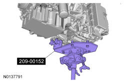
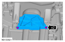
Install the transmission on the engine dowels. Special Tool(s): Adapter, Transmission Jack 209-00152. General equipment: Transmission jack.
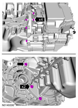
- 12.
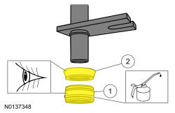
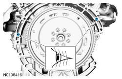
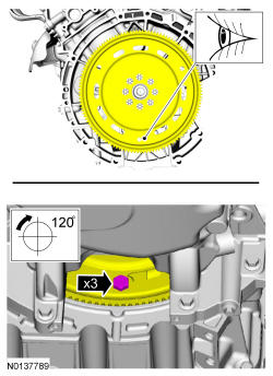
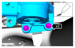
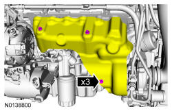
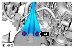
Install 3 new torque converter bolts (W714722).- Install the first torque converter bolt in the slotted hole on the flexplate.
- Tighten to 55 Nm (41 lb-ft).
NOTE:
Use only the specified bolts for the torque converter. Standard length fasteners may bottom out and damage the torque converter clutch apply surface.
- 14.
Install the PTU. REFER to Transfer Case Power Transfer Unit (PTU) .
- 16.
Install a new halfshaft seal. REFER to, Halfshaft Seal - LH .
NOTE:
If the transmission has been replaced or overhauled, the halfshaft seals do not need to be replaced.
- 17.
Using part: AA5P-4N206-A.
NOTE:
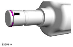
Remove the seal protector before the halfshaft is installed completely.
- 18.
NOTE:
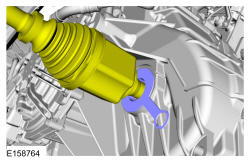
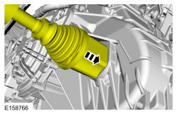
Insert shaft until circlip is fully seated. When checking if circlip is seated do not pull on CV joint or damage can result.
NOTE:
After insertion, pull the halfshaft inner end to make sure the circlip is locked.
- 19.
Install the front subframe. REFER to Uni-Body, Subframe and Mounting System .
- 20.
Install the roll restrictors. Refer to Transmission Support Insulator - Anti-Roll, 3.5L GTDI .
- 23.
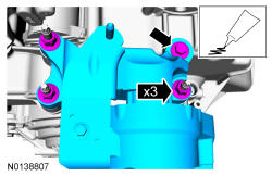
Material: Threadlock and Sealer TA-25.- Tighten the bolt to 80 Nm (59 lb-ft).
- Tighten the nuts to 63 Nm (46 lb-ft).
- 36.
- Tighten the starter battery terminal nut to 12 Nm (106 lb-in).
- Tighten the starter solenoid terminal nut to 6 Nm (53 lb-in).

- 41.
Install the cowl panel grille. REFER to Front End Body Panels .
- 42.
Adjust the selector lever cable. REFER to Automatic Transaxle Transmission External Controls - Transmission Control Switch (TCS) for console shift or REFER to Automatic Transaxle-Transmission External Controls Column Shift for column shift.
- 43.
Install the battery tray. REFER to Battery, Mounting and Cables .
- 44.
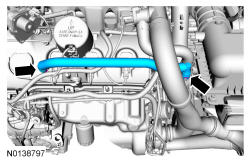
Install the ACL outlet pipe. REFER to Intake Air Distribution and Filtering .
- 45.
Fill the transmission with clean transmission fluid. Refer to Transmission Fluid Drain and Refill .
- 46.
If a new solenoid body is installed, the solenoid body strategy will need to be updated. Refer to Solenoid Body Strategy Download .