Turbine Shaft Speed (TSS) Sensor: Installation
- 1.
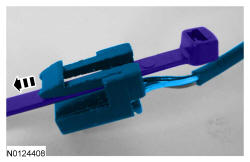
Route a plastic tie strap through the electrical connector of the new TSS sensor electrical connector.
NOTE:
Use a plastic tie strap big enough so that the locking end can not fit through the TSS sensor electrical connector and long enough so that it can be fed through the transmission case to pull the TSS electrical connector through the transmission case.
- 2.
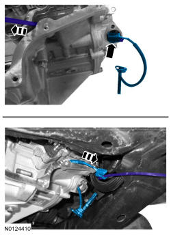
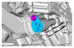
Route the plastic tie strap through the TSS sensor hole and route the tie strap to the main control valve body area. Use the tie strap to pull the TSS sensor electrical connector through the transmission case to the main control valve body area. Remove the tie strap from the TSS sensor.
NOTE:
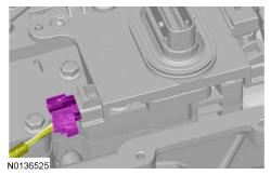
When routing the TSS sensor electrical connector through the transmission case, position the TSS sensor electrical connector locking tab toward the bottom of the TSS sensor hole.
- 5.
Install the main control cover. For 3.5L GTDI refer to, Main Control Cover - 3.5L GTDI . For 3.5L Ti-VCT refer to, Main Control Cover - 3.5L Ti-VCT .