Component Description
Transmission Fluid Filter
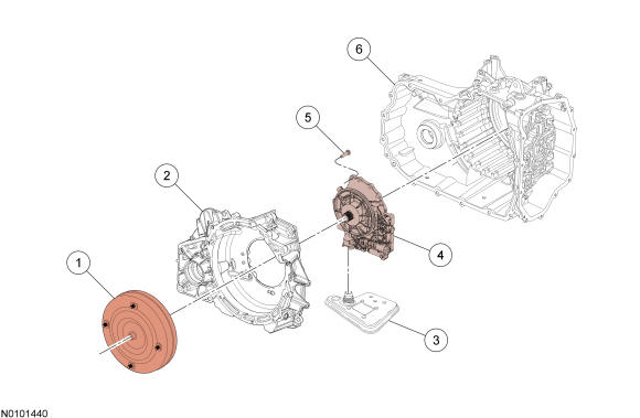
The transmission fluid in the sump area at the bottom of the transmission case flows through a transmission fluid filter to the pump assembly. The pump is bolted to the torque converter housing and is driven by the torque converter hub.
Fluid Pump and Transmission Fluid Filter Components
| Item | Description |
|---|---|
| 1 | Torque converter |
| 2 | Torque converter housing |
| 3 | Transmission fluid filter |
| 4 | Pump assembly |
| 5 | Pump-to-torque converter housing bolt |
| 6 | Transmission case |
Transmission Fluid Pump
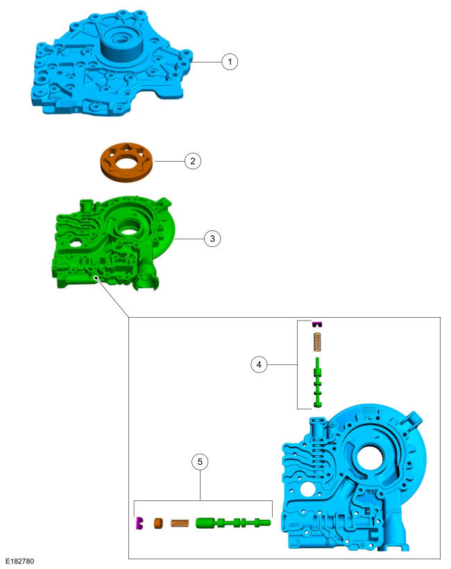
The pump assembly contains the main pressure regulator valve assembly, the TCC control valve assembly, the stator support and the pump gears.
Fluid Pump Components
| Item | Description |
|---|---|
| 1 | Stator support |
| 2 | Pump gears |
| 3 | Pump housing |
| 4 | TCC control valve assembly |
| 5 | Main pressure regulator valve assembly |
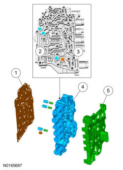
Main Control
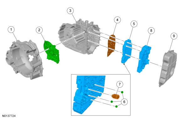
The hydraulic system has a main control assembly. The main control assembly consists of a valve body and a solenoid body. Both the valve body and the solenoid body contain hydraulic shift valves. The solenoid body contains the shift solenoids that control the hydraulic valves. The solenoid body can be serviced as an assembly with the solenoids or the solenoids can be serviced individually. The solenoid body is controlled by the TCM. The TCM has software stored in it specific to the solenoid body currently in the transmission, called the solenoid body strategy. A new solenoid body strategy must be downloaded into the TCM anytime a new solenoid body is installed.
The pump assembly contains the main pressure regulator valve assembly and the TCC control valve assembly.
Main Control Components
| Item | Description |
|---|---|
| 1 | Torque converter housing |
| 2 | Pump assembly |
| 3 | Transmission case |
| 4 | Main control-to-transmission case separator plate |
| 5 | Valve body |
| 6 | Check balls |
| 7 | Solenoid damper (SSA) |
| 8 | Solenoid body assembly |
| 9 | Main control cover |
Main Control Valve Body
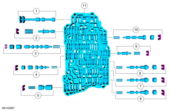
| Item | Description |
|---|---|
| 1 | Manual valve |
| 2 | Solenoid pressure regulator valve assembly |
| 3 | Clutch bypass valve |
| 4 | TCC regulator valve |
| 5 | Control pressure regulator |
| 6 | Direct (3, 5, R) clutch regulator valve |
| 7 | Intermediate (2, 6) clutch regulator valve |
| 8 | Forward (1, 2, 3, 4) clutch regulator valve |
| 9 | Forward (1, 2, 3, 4) clutch latch valve |
| 10 | Low reverse/overdrive (4, 5, 6) clutch regulator valve |
| 11 | Valve body |
Solenoid Body
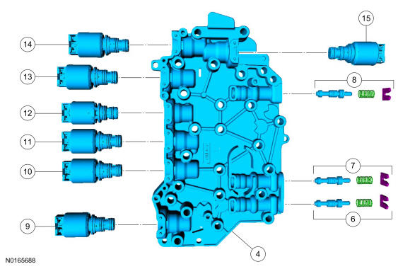
| Item | Description |
|---|---|
| 1 | Main control valve body-to-solenoid body separator plate |
| 2 | Damper pistons and springs |
| 3 | Elastomeric damper |
| 4 | Solenoid body |
| 5 | Solenoid body leadframe |
| 6 | Direct (3, 5, R) clutch latch valve |
| 7 | Intermediate (2, 6) clutch latch valve |
| 8 | Low reverse/overdrive (4, 5, 6) clutch latch valve |
| 9 | LPC solenoid |
| 10 | SSC |
| 11 | TCC |
| 12 | ON/OFF solenoid |
| 13 | SSA |
| 14 | SSB |
| 15 | SSD |
Multi-Plate Clutch
Multi-plate clutches are clutches that consist of multiple friction and steel clutch discs that when pressure is applied, either drive or hold (brake) components of the planetary gearset. This transmission has 5 multi-plate clutches:
- Forward (1, 2, 3, 4)
- Direct (3, 5, R)
- Intermediate (2, 6)
- Overdrive (4, 5, 6)
- Low/reverse
Both the direct (3, 5, R) and the overdrive (4, 5, 6) clutches are drive clutches. The direct (3, 5, R) clutch drives the rear planetary sun gear and the overdrive (4, 5, 6) clutch drives the rear planetary carrier. The forward (1, 2, 3.4), intermediate (2, 6) and the low/reverse clutches are brake clutches. The forward (1, 2, 3, 4) clutch holds the front sun gear, the intermediate (2, 6) clutch holds the rear sun gear and the low/reverse clutch holds the rear planetary carrier.
Clutches; overdrive (4, 5, 6) and direct (3, 5, R) are balanced in terms of dynamic pressure. That is, their pistons are exposed to the transmission fluid flow on both sides to prevent pressure buildup in the clutch as speed increases. This dynamic pressure equalization process is achieved by a baffle plate and pressure-free transmission fluid supply by a lubricating passage, through which the space between the piston and baffle plate is filled with transmission fluid.
The advantages of this dynamic pressure equalization are:
- reliable clutch engagement and release in all speed ranges.
- improved shift refinement.
External Sealing
The torque converter housing has a lip-type seal that seals the torque converter hub. The pump assembly seals to the torque converter housing with a rubber seal. The manual shaft and halfshafts also use liptype seals.
The torque converter housing is sealed to the transmission case with silicone sealant.
The main control cover is sealed to the transmission case with silicone sealant and seals to the solenoid body with a reusable rubber gasket. The TSS sensor is sealed to the transmission case with an O-ring seal.
The line pressure tap plug and transmission fluid drain plug have pipe threads and seal when tightened to specification.
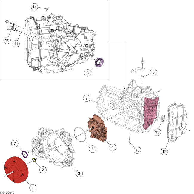
| Item | Description |
|---|---|
| 1 | Torque converter |
| 2 | Torque converter hub seal |
| 3 | Torque converter housing |
| 4 | Pump assembly |
| 5 | Pump assembly-to-torque converter housing O-ring seal |
| 6 | Manual control shaft seal |
| 7 | RH halfshaft seal |
| 8 | LH halfshaft seal |
| 9 | Transmission case |
| 10 | TSS sensor |
| 11 | TSS sensor O-ring seal |
| 12 | Main control cover |
| 13 | Main control-to-cover seal |
| 14 | Line pressure tap plug |
| 15 | Drain plug |
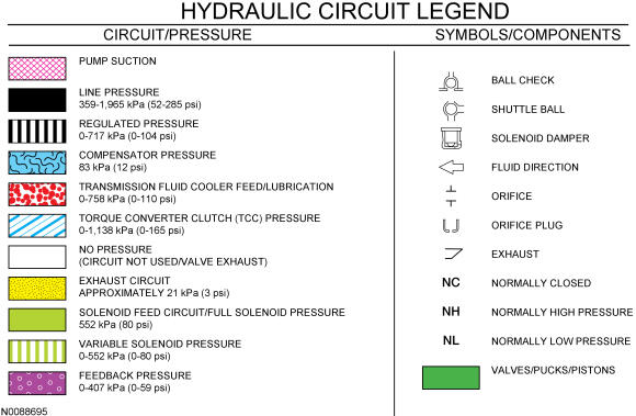
Hydraulic Circuits Legend
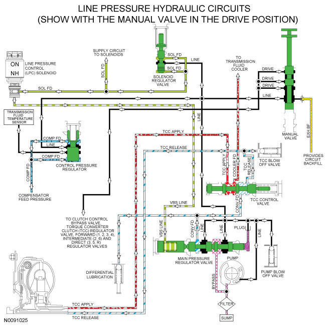
Line Pressure Hydraulic Circuits
Line pressure is controlled by the LPC solenoid, which is controlled by the TCM. This effects shift feel and apply component operation.
When the engine is running, the pump supplies pressure to the main pressure regulator valve, which is controlled by the LPC solenoid. The main pressure regulator valve controls the line pressure to the LINE circuit which supplies the manual valve solenoid regulator valve and the control pressure regulator valve.
When the manual valve is in the reverse position, it supplies the clutch control bypass valve with line pressure to position it to supply line pressure to the direct (3, 5, R) regulator valve and regulated line pressure to the low/reverse clutch to apply the clutch.
When the manual valve is in the DRIVE or LOW positions, it directs line pressure from the LINE circuit to the DRIVE circuit to supply line pressure to the:
- Clutch control bypass valve
- Forward (1, 2, 3, 4) regulator valve
- Intermediate (2, 6) regulator valve
- TCC regulator valve
- Direct (3, 5, R) clutch regulator valve
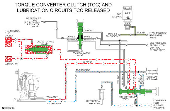
TCC and Lubrication Hydraulic Circuits
Pressure for TCC release is supplied by the main pressure regulator valve to the TCC control valve through the CONV FD circuit. The CONV FD circuit also supplies lubrication for the differential. When the TCC is released, the TCC control valve is positioned by the TCC solenoid to direct CONV FD pressure to the TCC RELEASE circuit to release the TCC. TCC RELEASE pressure returns to the TCC control valve through the TCC APPLY circuit. The position of the TCC control valve opens the TCC APPLY circuit to the COOLER FD circuit which allows the transmission fluid returned from the torque converter to cycle through the thermal bypass valve circuit when the TFT is below 80 °C-93 ° C (176 °F-200 ° F) or the transmission fluid cooler when the temperature is above 80 ° C-93 ° C (176 ° F-200 ° F).
Return transmission fluid from the thermal bypass valve or the transmission fluid cooler supplies transmission lubrication through the LUBE circuit which runs through the input shaft.
For lubrication passage location and description, refer to Hydraulic Circuit Identification Chart in this article.
The position of the TCC control valve is controlled by pressure from the TCC solenoid through the VBS TCC circuit. The TCC solenoid is controlled by the PCM.
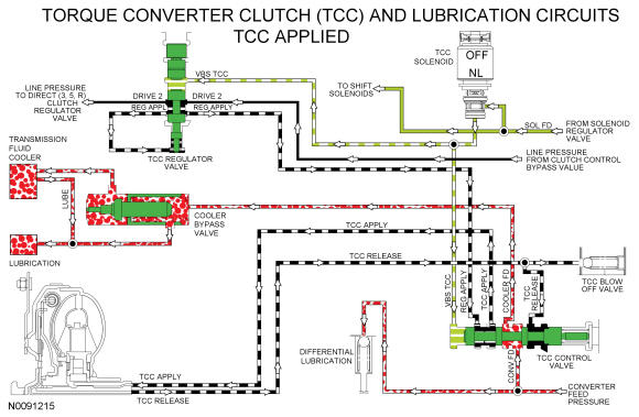
When the TCC clutch is applied, the TCC solenoid applies pressure to the TCC control and regulator valves to position the valves to apply the TCC clutch. Regulated line pressure is supplied to the TCC control valve through the REG APPLY circuit by the TCC regulator valve. The TCC control valve directs the regulated line pressure from the REG APPLY circuit to the TCC APPLY circuit to apply the TCC. The TCC control valve blocks the TCC RELEASE circuit to maintain pressure in the TCC APPLY circuit. The TCC control valve directs the CONV FD circuit to the COOLER FD circuit to allow the transmission fluid to flow through the thermal bypass valve or the transmission fluid cooler to the LUBE circuit to lubricate the transmission.
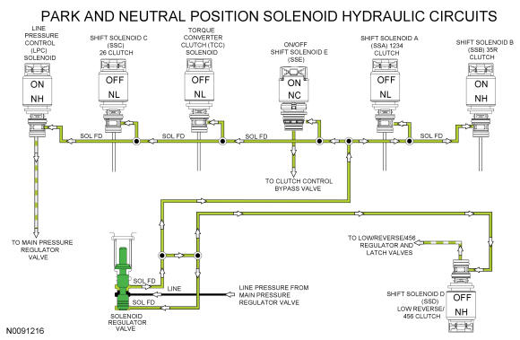
Solenoid Hydraulic Circuits
Line pressure from the main pressure regulator valve is directed to the individual shift, TCC and LPC solenoids by the solenoid regulator valve through the SOL FD circuit. The solenoids, controlled by the TCM, direct the fluid to the valves that they control.
The LPC solenoid applies varying pressure to the main pressure regulator valve to control line pressure.
In the PARK and NEUTRAL positions, SSD applies varying pressure to the low reverse/456 regulator and latch valves through the VBS CBR1/456 hydraulic circuit to position the valves to apply the low/reverse clutch. ON/OFF SSE directs pressure to the clutch control bypass valve to position the valve to direct regulated line pressure from the low reverse/456 regulator valve to the low/reverse clutch.
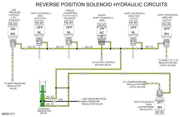
In the REVERSE position, SSD applies varying pressure to the low reverse/456 regulator and latch valves through the VBS CBR1/456 hydraulic circuit to position the valves to apply the low/reverse clutch. ON/OFF SSE directs pressure to the clutch control bypass valve to position the valve to direct regulated line pressure from the low reverse/456 regulator valve to the low/reverse clutch. The clutch control bypass valve also directs line pressure from the REVERSE circuit to the 35R regulator valve through the C35R FD and DRIVE 2/C35R FD circuits. SSB directs varying pressure to the 35R regulator and latch valves through the VBS C35R hydraulic circuit to apply the direct (3, 5, R) clutch.
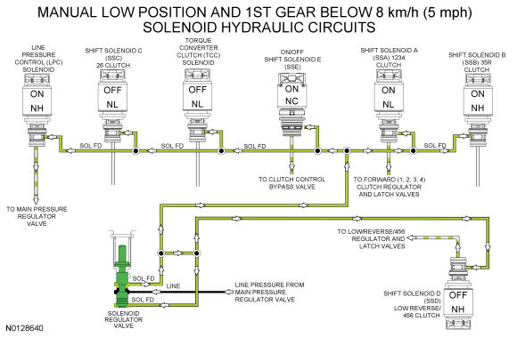
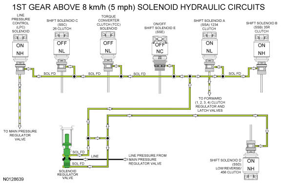
In 1st gear, SSA applies varying pressure to the 1234 clutch regulator and latch valves through the VBS C1234 hydraulic circuit to apply the forward (1, 2, 3, 4) clutch.
When vehicle speed is below 8 km/h (5 mph), or the selector lever is in the manual low position, SSD applies varying pressure to the low reverse/456 regulator and latch valves through the VBS CBR1/456 hydraulic circuit to position the valves to apply the low/reverse clutch. ON/OFF SSE directs pressure to the clutch control bypass valve to position the valve to direct regulated line pressure from the low reverse/456 regulator valve to the low/reverse clutch. As vehicle speed increases above 8 km/h (5 mph) in 1st gear, SSD removes pressure from the low reverse/456 regulator and latch valves and SSE removes pressure from the clutch control bypass valve to release the low/reverse clutch.
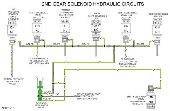
In 2nd gear, the forward (1, 2, 3, 4) clutch remains applied. SSC applies varying pressure to the 26 regulator and latch valves through the VBS CB26 hydraulic circuit to apply the intermediate (2, 6) clutch.
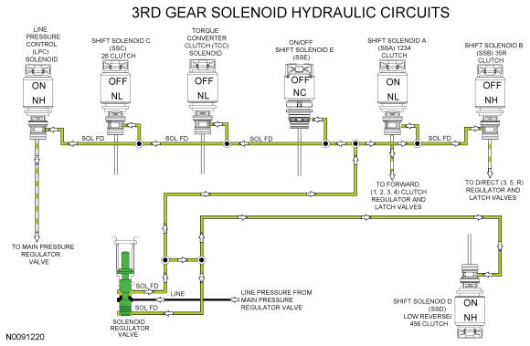
In 3rd gear, the forward (1, 2, 3, 4) clutch remains applied. SSC releases pressure to the 26 regulator and latch valves to release the intermediate (2, 6) clutch. SSB directs pressure to the 35R regulator and latch valves through the VBS CB26 hydraulic circuit to apply the direct (3, 5, R) clutch.
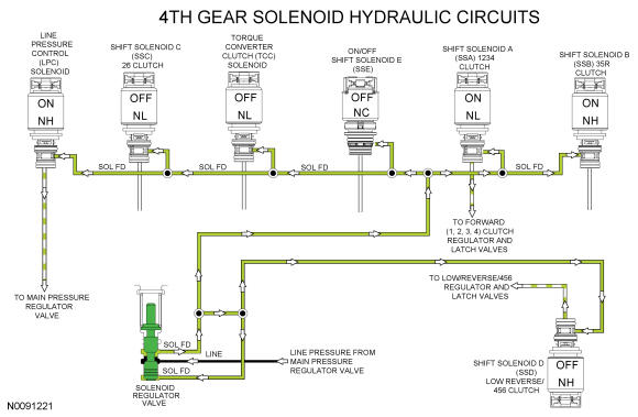
In 4th gear, the forward (1, 2, 3, 4) clutch remains applied. SSB releases pressure to the 35R regulator and latch valves. SSD directs pressure to the low reverse/456 regulator and latch valves through the VBS CBR1/456 hydraulic circuit. With SSE released, the clutch control bypass valve directs the regulated line pressure from the low reverse/456 regulator valve to the O/D (4, 5, 6) clutch to apply the clutch.
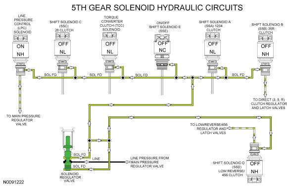
In 5th gear, the O/D (4, 5, 6) clutch remains applied. SSA releases pressure to the 1234 regulator and latch valves to release the forward (1, 2, 3, 4) clutch. SSB directs pressure to the 35R regulator and latch valves through the VBS C35R hydraulic circuit to apply the direct (3, 5, R) clutch.
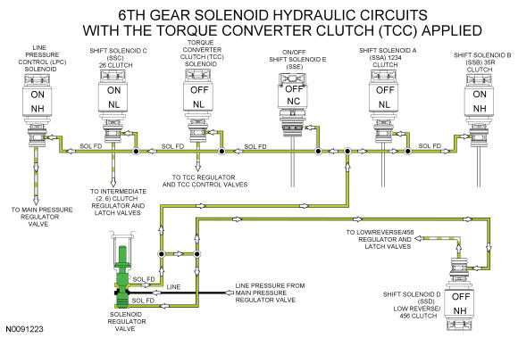
In 6th gear, the O/D (4, 5, 6) clutch remains applied. SSB releases pressure to the 35R regulator and latch valves. SSC applies varying pressure to the 26 clutch regulator and latch valves through the VBS CB26 hydraulic circuit to apply the intermediate (2, 6) clutch.
The TCC can be applied in 4th, 5th or 6th gear. To apply the TCC, the TCC solenoid applies pressure to the TCC regulator valve and the TCC control valve to position the valves to apply the clutch.
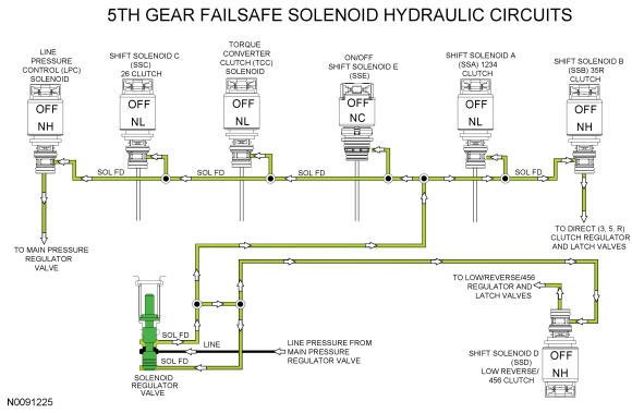
During a mechanical, hydraulic or electrical failure with the manual lever in the DRIVE position, the transmission defaults to 5th gear. When the transmission is in 5th gear failsafe, the PCM does not control the shift solenoids and they default to their normal state (maximum pressure, minimum pressure, on or off). The LPC solenoid defaults to maximum pressure, SSA defaults to minimum pressure, SSB defaults to maximum pressure, SSC defaults to minimum pressure, SSD defaults to maximum pressure and the TCC solenoid defaults to minimum pressure.
With SSB applying maximum pressure to the direct (3, 5, R) regulator and latch valves, the direct (3, 5, R) clutch is applied. With SSD applying maximum pressure to the low reverse/456 regulator and latch valves with SSE in the OFF position, the O/D (4, 5, 6) clutch is applied, providing 5th gear.
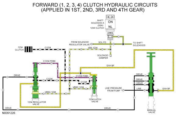
Forward (1, 2, 3, 4) Clutch Hydraulic Circuits
Line pressure is supplied to the 1234 regulator valve by the manual valve in the DRIVE and LOW position. To apply the forward (1, 2, 3, 4) clutch, SSA supplies varying solenoid pressure to the 1234 regulator and latch valves. As the regulator valve moves, it supplies the forward (1, 2, 3, 4) clutch and 1234 latch valve with regulated line pressure through the C1234 circuit. The 1234 latch valve directs the regulated line pressure to the opposite side of the 1234 regulator valve through the C1234 FDBK circuit for gradual forward (1, 2, 3, 4) clutch engagement. The forward (1, 2, 3, 4) clutch is applied in 1st, 2nd, 3rd and 4th gears and manual LOW position.
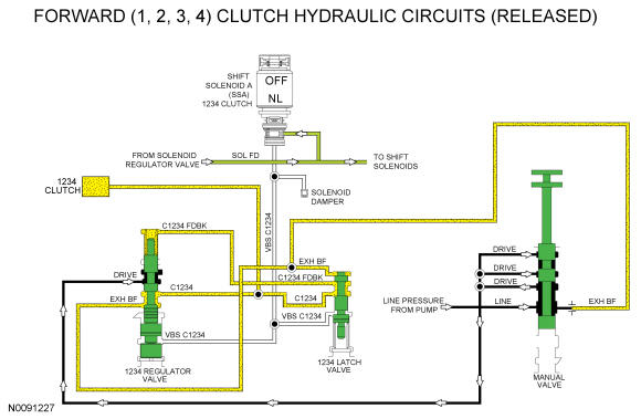
When the forward (1, 2, 3, 4) clutch is released in 5th and 6th gears, solenoid pressure from SSA is removed from the 1234 regulator and latch valves which positions the valves to block line pressure and release the forward (1, 2, 3, 4) clutch. When the forward (1, 2, 3, 4) clutch is released in the PARK, REVERSE or NEUTRAL position, line pressure is not supplied to the forward (1, 2, 3, 4) regulator valve.
In the released position, exhaust backfill supplied to the 1234 regulator and latch valves by the manual valve through the EXH BF circuit is directed to the forward (1, 2, 3, 4) clutch to fill the unused circuits with unpressurized transmission fluid.
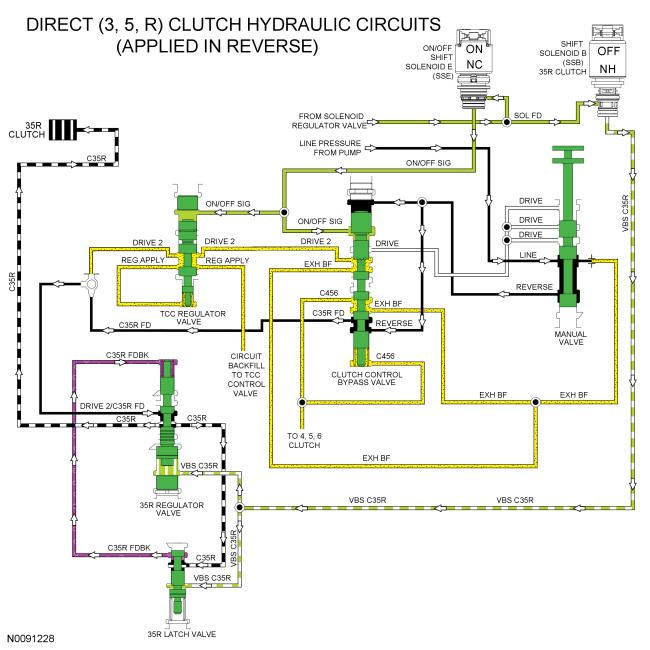
Direct (3, 5, R) Clutch Hydraulic Circuits
When the direct (3, 5, R) clutch is applied in the REVERSE position, line pressure from the manual valve is directed to the clutch control bypass valve through the REVERSE circuit. Line pressure in the REVERSE circuit positions the clutch control bypass valve and supplies line pressure to apply the direct (3, 5, R) clutch. Line pressure from the clutch control bypass valve is supplied to the 35R regulator valve through the C35R FD circuit, DRIVE 2/C35R FD shuttle ball and DRIVE 2/C35R FD circuit.
To apply the direct (3, 5, R) clutch, SSB applies varying solenoid pressure to the 35R regulator and latch valves. As the regulator valve moves, it supplies the direct (3, 5, R) clutch and 35R latch valve with regulated line pressure through the C35R circuit. The 35R latch valve directs the regulated line pressure to the opposite side of the 35R regulator valve through the C35R FDBK circuit for gradual direct (3, 5, R) clutch engagement.
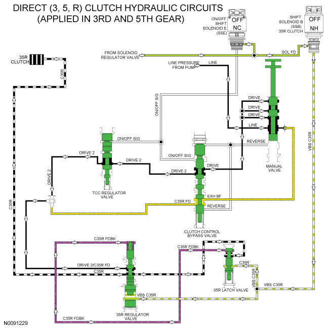
When the direct (3, 5, R) clutch is applied in 3rd and 5th gear, line pressure from the pump is directed to the clutch control bypass valve by the manual valve through the DRIVE hydraulic circuit. The clutch control bypass valve directs the pressure to the 35R regulator valve through the TCC regulator valve, DRIVE 2 circuit, DRIVE 2/C35R FD shuttle ball and DRIVE 2/C35R FD circuit.
To apply the direct (3, 5, R) clutch, SSB applies varying solenoid pressure to the 35R regulator and latch valves. As the 35R regulator valve moves, it supplies the direct (3, 5, R) clutch and 35R latch valve with regulated line pressure through the C35R circuit. The 35R latch valve directs the regulated line pressure to the opposite side of the regulator valve through the C35R FDBK circuit for gradual direct (3, 5, R) clutch engagement.
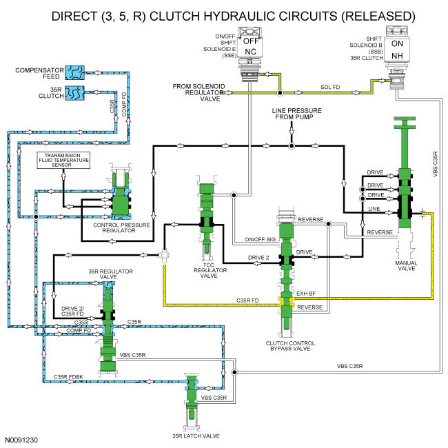
When the direct (3, 5, R) clutch is released, solenoid pressure from SSB is removed from the 35R regulator and latch valves which positions the valves to block line pressure and release the direct (3, 5, R) clutch. When the direct (3, 5, R) clutch is released in the PARK or NEUTRAL position, line pressure is not supplied to the 35R regulator valve.
Compensator feed pressure is supplied to the 35R regulator valve from the control pressure regulator through the COMP FD circuit and is supplied to the opposite side of the direct (3, 5, R) and O/D (4, 5, 6) clutch pistons to keep the clutches from centrifugally applying. COMP FD pressure is only about 83 kPa (12 psi) and is applied through all gears. When the direct (3, 5, R) clutch is released, COMP FD is applied by the 35R regulator valve to the direct (3, 5, R) clutch to fill the unused circuits.
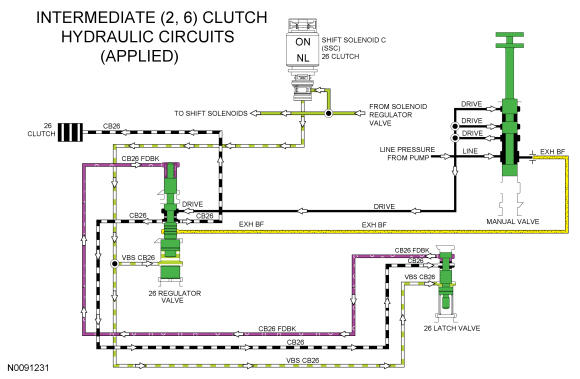
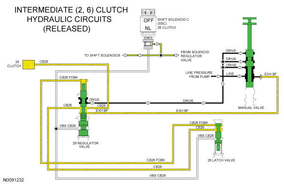
Intermediate (2, 6) Clutch Hydraulic Circuits
Line pressure is supplied to the 26 regulator valve by the manual valve in the DRIVE and LOW positions. To apply the intermediate (2, 6) clutch, SSC supplies varying solenoid pressure to the 26 regulator and latch valves. As the 26 regulator valve moves, it supplies the intermediate (2, 6) clutch and 26 latch valve with regulated line pressure through the CB26 circuit. The 26 latch valve directs the regulated line pressure to the opposite side of the 26 regulator valve through the CB26 FDBK circuit for gradual intermediate (2, 6) clutch engagement. The intermediate (2, 6) clutch is applied in 2nd and 6th gears.
When the intermediate (2, 6) clutch is released in 1st, 3rd, 4th and 5th gears and manual LOW position, solenoid pressure from SSC is removed from the 26 regulator and latch valves which positions the valves to block line pressure and release the intermediate (2, 6) clutch. When the intermediate (2, 6) clutch is released in the PARK, REVERSE or NEUTRAL position, line pressure is not supplied to the 26 regulator valve.
In the released position, exhaust backfill supplied to the 26 clutch regulator valve by the manual valve through the EXH BF circuit is directed to the intermediate (2, 6) clutch and 26 latch valve to fill the unused circuits with unpressurized transmission fluid.
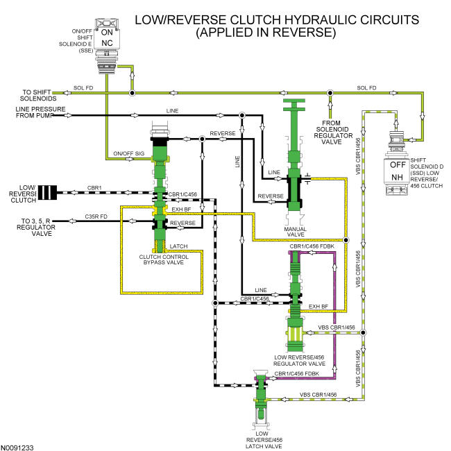
Low/Reverse Clutch Hydraulic Circuits
Line pressure is supplied to the low reverse/456 regulator valve by the pump in every gear and manual lever position. To apply the low/reverse clutch, SSD supplies varying solenoid pressure to the low reverse/456 regulator and latch valves. As the low reverse/456 regulator valve moves, it supplies the clutch control bypass valve and low reverse/456 latch valve with regulated line pressure through the CBR1/C456 circuit. The low reverse/456 latch valve directs the regulated line pressure to the opposite side of the 456 regulator valve through the CBR1/C456 FDBK circuit for gradual low reverse/456 clutch engagement. The low/reverse clutch is applied in PARK, REVERSE, NEUTRAL, 1st gear below 8 km/h (5 mph) and manual LOW position.
In REVERSE, both solenoid pressure from ON/OFF SSE and line pressure from the manual valve in the REVERSE circuit apply pressure to the clutch control bypass valve to position it for low/reverse clutch application. Regulated line pressure from the CBR1/C456 circuit is directed to the low/reverse clutch by the clutch control bypass valve through the CBR1 circuit to apply the low/reverse clutch.
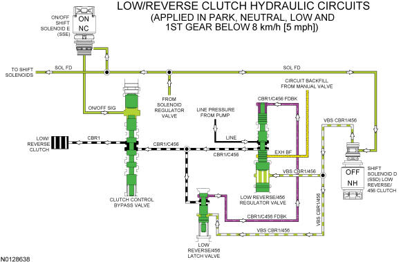
When the low/reverse clutch is applied in PARK, NEUTRAL, LOW or 1st gear below 8 km/h (5 mph), only pressure from ON/OFF SSE, positions the clutch control bypass valve. Line pressure from the REVERSE circuit is not supplied by the manual valve.
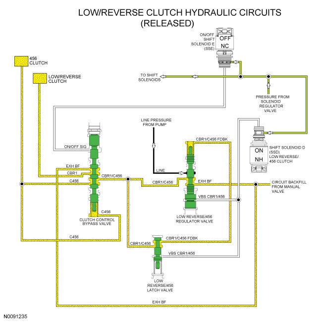
When the low/reverse clutch is released in 1st gear above 8 km/h (5 mph), 2nd and 3rd gears, solenoid pressure from SSD is removed from the low reverse/456 regulator and latch valves which positions the valves to block line pressure and release the low/reverse clutch. Solenoid pressure from SSE is removed from the clutch control bypass valve to position it to apply the O/D (4, 5, 6) clutch.
When the low/reverse clutch is released in 1st gear above 8 km/h (5 mph), 2nd and 3rd gears, exhaust backfill supplied to the low reverse/456 clutch regulator valve and the clutch control bypass valve by the manual valve through the EXH BF circuit is directed to the low reverse/456 latch valve, low/reverse clutch and O/D (4, 5, 6) clutch to fill the unused circuits with unpressurized transmission fluid.
When the low/reverse clutch is released in 4th, 5th and 6th gears, the low reverse/456 regulator valve supplies regulated pressure to the clutch control bypass valve through the CBR1/C456 circuit. With ON/OFF SSE in the OFF position, the regulated pressure is directed to the O/D (4, 5, 6) clutch.
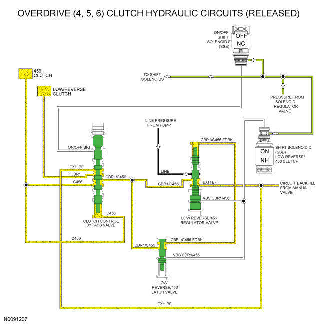
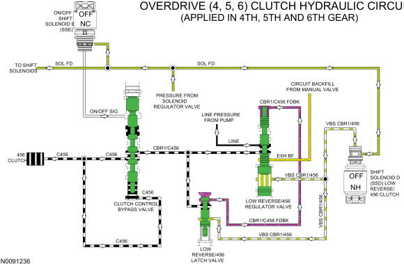
Overdrive (4, 5, 6) Clutch Hydraulic Circuits
Line pressure is supplied to the low reverse/456 regulator valve by the pump in every gear and manual lever position. To apply the low/reverse clutch, SSD supplies varying solenoid pressure to the low reverse/456 regulator and latch valves. As the regulator valve moves, it supplies the clutch control bypass valve and low reverse/456 latch valve with regulated line pressure through the CBR1/C456 circuit. The low reverse/456 latch valve directs the regulated line pressure to the opposite side of the low reverse/456 regulator valve through the CBR1/C456 FDBK circuit for gradual O/D (4, 5, 6) clutch engagement.
To apply the O/D (4, 5, 6) clutch, the position of the clutch control bypass valve allows the regulated line pressure in the CBR1/C456 circuit to supply the C456 circuit, applying the O/D (4, 5, 6) clutch. Clutch control bypass valve latch pressure is supplied by the C456 circuit. The O/D (4, 5, 6) clutch is applied in 4th, 5th and 6th gears.
When the O/D (4, 5, 6) clutch is released in 1st gear above 8 km/h (5 mph), 2nd and 3rd gears, solenoid pressure from SSD is removed from the low reverse/456 regulator and latch valves which positions the valves to block line pressure and release the O/D (4, 5, 6) clutch.
When the O/D (4, 5, 6) clutch is released in 1st gear above 8 km/h (5 mph), 2nd and 3rd gears, exhaust backfill supplied to the low reverse/456 clutch regulator valve and the clutch control bypass valve by the manual valve through the EXH BF circuit is directed to the low reverses latch valve, low/reverse clutch and O/D (4, 5, 6) clutch to fill the unused circuits with unpressurized transmission fluid.
When the O/D (4, 5, 6) clutch is released in PARK, REVERSE, NEUTRAL and 1st gear below 8 km/h (5 mph), the low reverse/456 regulator valve supplies regulated pressure to the clutch control bypass valve through the CBR1/C456 circuit. With ON/OFF SSE in the ON position, the regulated pressure is directed to the low/reverse clutch.