Main Control - Overhaul
WARNING: This page is about a different variant/trim than selected.
Special Tool(s)
| Pins, Leadframe Guide 307-636 |

| Item | Part Number | Description |
|---|---|---|
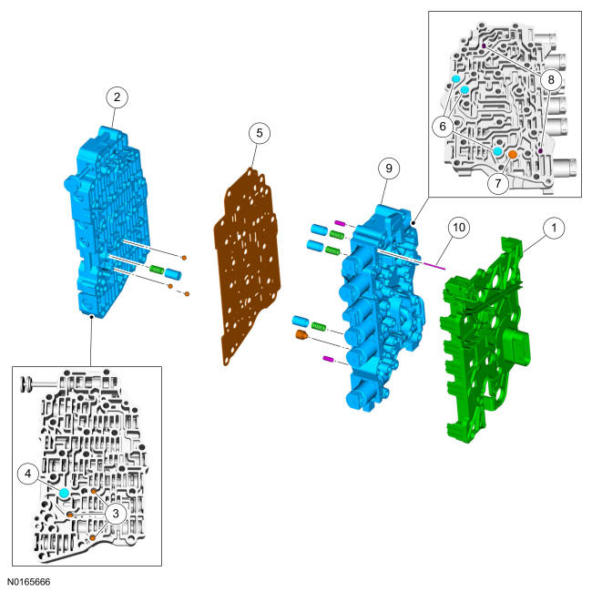
| 1 | 7G276 | Leadframe |
| 2 | 7A100 | Main control valve body |
| 3 | 7E195 | Check balls (3 required) |
| 4 | 7J191 | Solenoid damper (SSA) |
| 5 | 7Z490 | Solenoid body-to-valve body separator plate |
| 6 | 7J193 | Damper pistons and springs (3 required) |
| 7 | 7J191 | Elastomeric damper |
| 8 | - | Dowel pins (2 required) |
| 9 | 7G391 | Solenoid body |
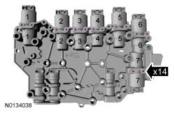
| 10 | 7H111 | Solenoid retaining pin (14 required) |
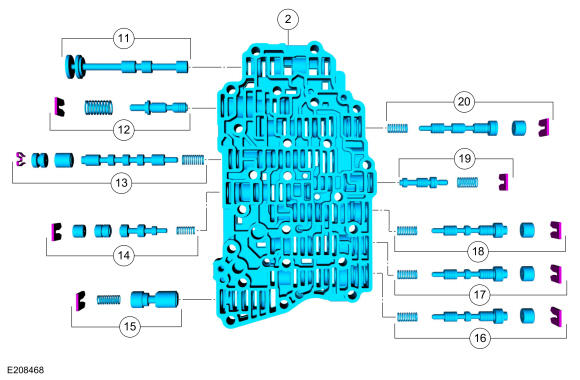
| 11 | 7C389 | Manual valve |
| 12 | 7G473 | Solenoid pressure regulator valve assembly |
| 13 | 7G179 | Clutch bypass valve |
| 14 | 7G307 | TCC regulator valve |
| 15 | 7B200 | Control pressure regulator |
| 16 | 7D102 | Direct (3, 5, R) clutch regulator valve |
| 17 | 7D102 | Intermediate (2, 6) clutch regulator valve |
| 18 | 7D102 | Forward (1, 2, 3, 4) clutch regulator valve |
| 19 | 7J187 | Forward (1, 2, 3, 4) clutch latch valve |
| 20 | 7D102 | Low reverse/overdrive (4, 5, 6) clutch regulator valve |
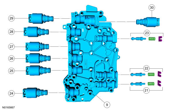
| 21 | 7J187 | Direct (3, 5, R) clutch latch valve |
| 22 | 7J187 | Intermediate (2, 6) clutch latch valve |
| 23 | 7J187 | Low reverse/overdrive (4, 5, 6) clutch latch valve |
| 24 | 7G383 | LPC solenoid |
| 25 | 7G136 | SSC |
| 26 | 7G136 | TCC solenoid |
| 27 | 7G484 | SSE ON/OFF solenoid |
| 28 | 7G136 | SSA |
| 29 | 7G383 | SSB |
| 30 | 7G383 | SSD |
Main Control Valve Body and Solenoid Body
Main Control Valve Body
- 5.
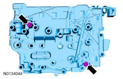
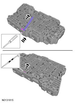
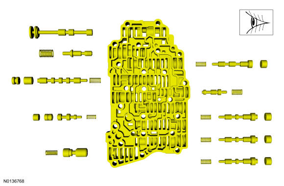
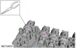
Compress the valve springs with a screwdriver and remove the retainers with a magnet. Use a pick to remove the bypass valve retainer. Remove the individual valves and springs from the main control valve body by tapping the valve body on the palm of the hand to slide the valves out of the bores. If needed, use a 4-mm bolt to thread into the valves to remove the valves. See the Valve Body illustration for valve and spring locations.
NOTE:
The bypass valve is held in with a spring-loaded retainer. Be careful not to lose the retainer when removing it.
NOTE:
Remove the valves by tapping the valve body on the palm of the hand to slide the valves out of the bores or by threading a 4-mm bolt into the valves and pulling them out. It may be necessary to remove the valves and springs using a pick. If it is necessary to use a pick, use extreme caution to prevent damaging the valves or valve bores. If necessary, disassemble parts of the main control valve body in small groups. Take special care when handling the main control components, since they are the most precise and delicate parts of the transmission. Neatly arrange the parts as they are removed to avoid mixing similar pieces.
- 6.
Clean the valves, springs and main control valve body.
NOTE:
Do not stone or polish any valves or damage to the valves can occur. If the valves do not move freely, install a new assembly.
- 7.
Install the valve body valves, springs and retaining clips in the main control valve body. See the Valve Body illustration at the beginning of this procedure for valve and spring locations.
NOTE:
Do not stone or polish any valves or damage to the valves can occur. If the valves do not move freely during assembly, install a new valve body.
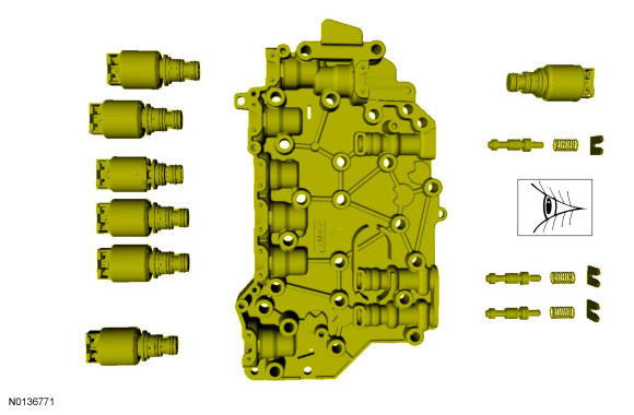
Solenoid Body
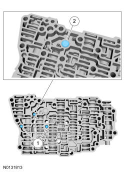
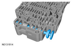
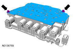
- 11.
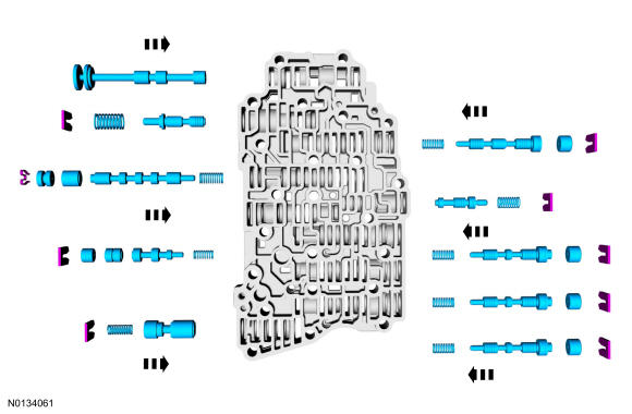
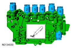
Compress the valve springs with a screwdriver and remove the retainers with a magnet. Remove the individual valves and springs from the solenoid body by tapping it on the palm of the hand to slide the valves out of the bores. See the Solenoid Body illustration at the beginning of this procedure for valve and spring locations.
- 12.
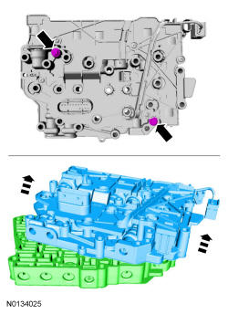
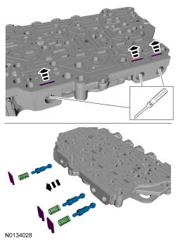
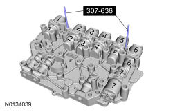
Remove the screws and carefully remove the leadframe from the solenoids by lifting it straight up evenly.
NOTE:
Be careful not to bend or twist the solenoid body leadframe or the solenoid terminals when removing the leadframe or damage can occur to the leadframe or the solenoids.
- 13.
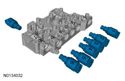
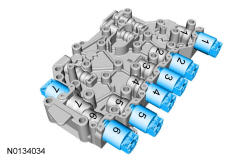
Using a paint marker, number the solenoids and the solenoid body to correspond with the ports from which the solenoids are located in the solenoid body.
NOTE:
The solenoids are calibrated from the factory and are not all the same. Failure to mark the solenoids to the ports they were originally in can result in mixing the solenoids and can cause damage to the transmission or a harsh shift.
- 16.
Clean and inspect the solenoid body, solenoids and valve assemblies for damage.
NOTE:
Do not stone or polish any valves or damage to the valves can occur. If the valves do not move freely during assembly, install a new solenoid body.
NOTE:
Be careful not to wash the numbers from the solenoids or the solenoid body. Failure to install the solenoids in the ports they were originally in can result in damage to the transmission or a harsh shift.
- 18.
If new solenoid(s) are not being installed, position the solenoids in the solenoid body ports from which their numbers correspond.
NOTE:
The solenoids are calibrated from the factory and are not all the same. Failure to install the solenoids in the ports they were originally in can result in damage to the transmission or a harsh shift.
- 19.
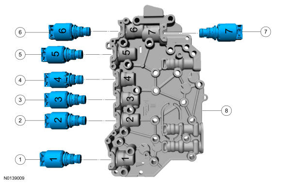
If installing a new VFS, determine the base part number of the solenoid(s). The TCC solenoid, SSA and SSC are all normally low pressure solenoids. The LPC solenoid, SSB and SSD are all normally high pressure solenoids. The SSE is not a VFS, it is an ON/OFF solenoid.Item Part Number Description 1 7G383 LPC solenoid (normally high) 2 7G136 SSC solenoid (normally low) 3 7G136 TCC (normally low) 4 7G484 SSE (normally closed [OFF]) 5 7G136 SSA (normally low) 6 7G383 SSB (normally high) 7 7G383 SSD solenoid (normally high) 8 7G391 Solenoid body
- 20.
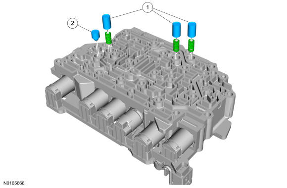
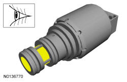
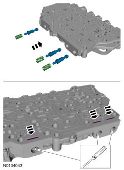
If installing new solenoids, note the color of the plastic nozzle and the large O-ring. High pressure solenoids, such as the LPC solenoid, SSB and SSD, have black plastic nozzles and orange O-rings. Low pressure solenoids, such as the TCC solenoid, SSA and SSC, have brown plastic nozzles and green O-rings. The solenoids can only be replaced with the same color solenoid.
- 21.
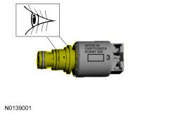
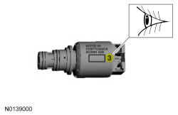
Determine the part number suffix by checking the solenoid service band number etched on the side of the solenoid. The band number is next to the two-dimensional matrix barcode on the side of the solenoid and will be a 1, 2, 3, 4 or 5. Determine the part number suffix and match the new solenoid base part number and suffix with the old solenoid.Solenoid Band Number Part Number Suffix 1 B 2 C 3 D 4 E 5 F
- 25.
Position the leadframe on the guide pins and carefully install the leadframe by pushing it straight down into the solenoids.
NOTE:
Be careful not to bend or twist the solenoid body leadframe or the solenoid terminals when installing the leadframe or damage can occur to the leadframe or the solenoids.
- 27.
Install the solenoid body valves, springs and retaining clips in the solenoid body. See the Solenoid Body illustration at the beginning of this procedure for valve and spring locations.
NOTE:
If the valves do not move freely during assembly, install a new solenoid body. Failure to install a new solenoid body can result in a harsh shift or damage to the transmission.
Main Control Valve Body and Solenoid Body
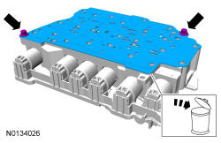
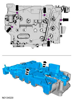
- 29.
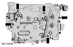
Install the new separator plate and the separator plate-to-solenoid body bolts.- Tighten to 10 Nm (89 lb-in).
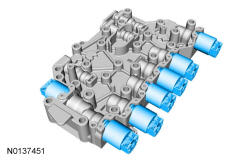
- 30.
Position the solenoid body assembly on the valve body and install the solenoid body-to-valve body bolts.- Tighten to 10 Nm (89 lb-in).