Output Shaft Seal: Installation

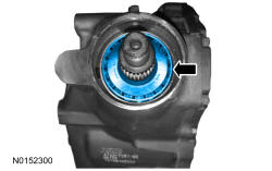
- 5.NOTE: Install the output pinion flange to engage the spline as previously marked. Install a new output pinion flange and deflector if the output shaft seal mating surface is damaged.
Install the output pinion flange.
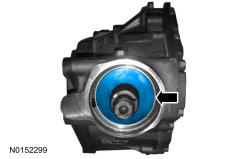
- 6.NOTE: Refer to the rotational torque previously recorded with the Nm (lb-in) torque wrench. Tighten the pinion nut in small increments until it is within 0.3 Nm (3 lb-in) of the reference measurement. If 0.3 Nm (3 lb-in) is exceeded, then the collapsible spacer will be damaged and a new collapsible spacer will be required.
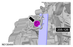
Using the 205-126 T78P-4851-A to hold the output pinion flange, install and tighten the new pinion flange nut.
- 7.
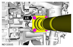
Using the index mark, position the driveshaft and install the 4 driveshaft-to-Power Transfer Unit (PTU) output flange bolts.- Tighten to 70 Nm (52 lb-ft).
- 8.
Install the front subframe. REFER to Uni-Body, Subframe and Mounting System .
- 9.
Fill the PTU as necessary. Refer to Power Transfer Unit (PTU) Draining and Filling .