Steering Gear: Removal
CAUTION:
Suspension fasteners are critical parts that affect performance of vital components and systems. Failure of these fasteners may result in major service expense. Use the same or equivalent parts if replacement is necessary. Do not use a replacement part of lesser quality or substitute design. Tighten fasteners as specified.
- If installing a new steering gear, connect the scan tool and upload the module configuration information from the PSCM .
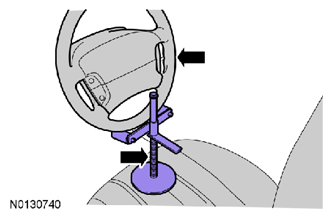
- Using a suitable holding device, hold the steering wheel in the straight-ahead position.
- Remove the front wheels and tires. REFER to REMOVAL .
-
NOTE:
If equipped.
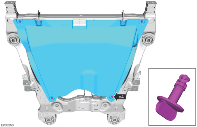
Remove the retainers and the skid plate.
-
NOTE:
If equipped.
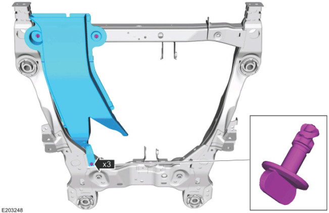
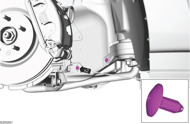
Remove the retainers and the underbody air duct.
-
NOTE:
If equipped.
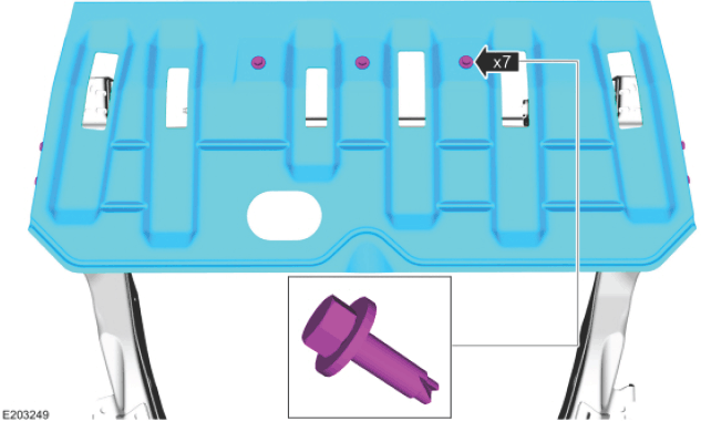
Remove the retainers and the underbody shield.
-
NOTE: On both sides.
Remove the wheel arch liner to front subframe retainers.
- Remove the exhaust flexible pipe. REFER to EXHAUST FLEXIBLE PIPE -- 2.0L GTDI .
- Remove the LH and RH exhaust flexible pipes. REFER to EXHAUST FLEXIBLE PIPE -- LH, 3.5L GTDI , or EXHAUST FLEXIBLE PIPE -- RH, 3.5L GTDI .
- Remove the exhaust Y-pipe. REFER to EXHAUST Y-PIPE -- 3.5L TI-VCT .
- Remove the exhaust Y-pipe. REFER to the appropriate Exhaust service information. .
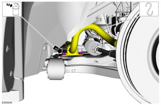
- Remove and discard the stabilizer bar bracket-to-front subframe bolts and support the stabilizer bar.
- On both side.
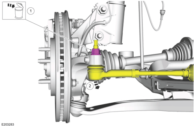
- Remove and discard the tie rod end nut.
- Separate the tie rod end from the wheel knuckle.
- Use Special Service Tool: 204-592 Separator, Lower Arm Ball Joint.
-
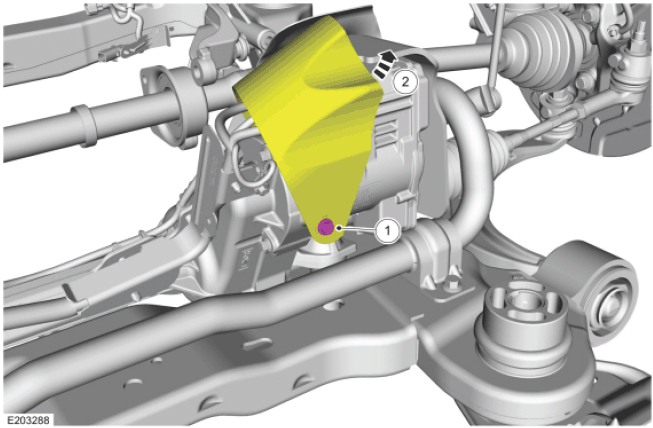
- Remove the Electronic Power Assist Steering (EPAS) gear flap heat shield bolt.
- Position aside the EPAS gear flap heat shield.
-
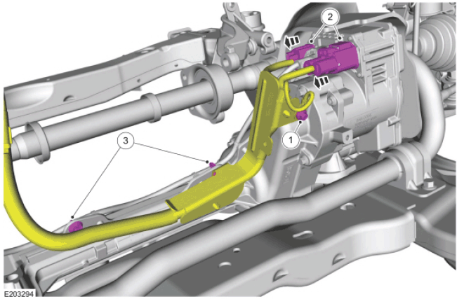
- Remove the EPAS gear harness ground bolt.
- Disconnect the EPAS gear harness electrical connectors.
- Unclip the EPAS gear harness and position aside.
-
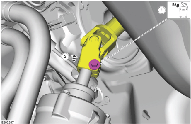
- Remove and discard the steering column shaft bolt.
- Separate the steering column shaft coupler from the EPAS gear.
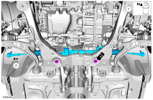
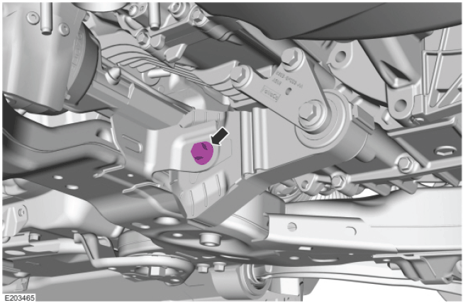
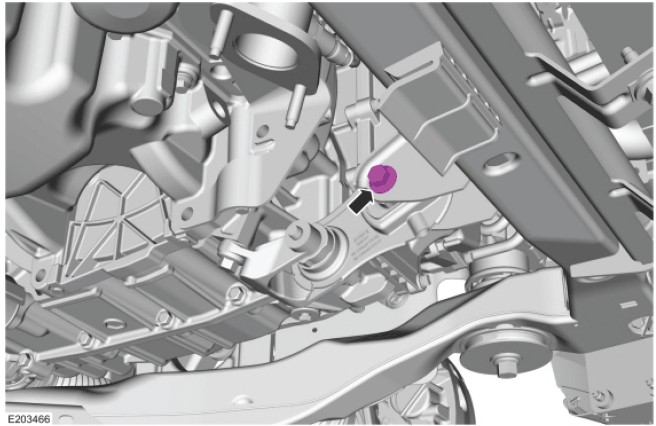
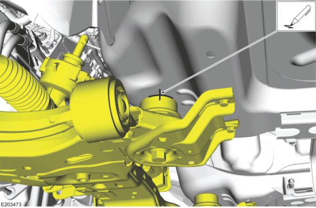
- Remove the rear roll restrictor-to-subframe bolt.
- Remove the roll restrictor-to-subframe bolt.
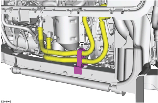
- Unclip the oil cooler hose retainer from the front subframe.
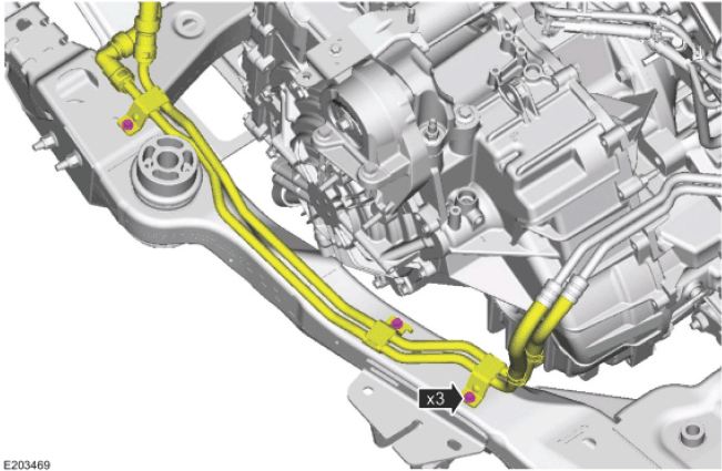
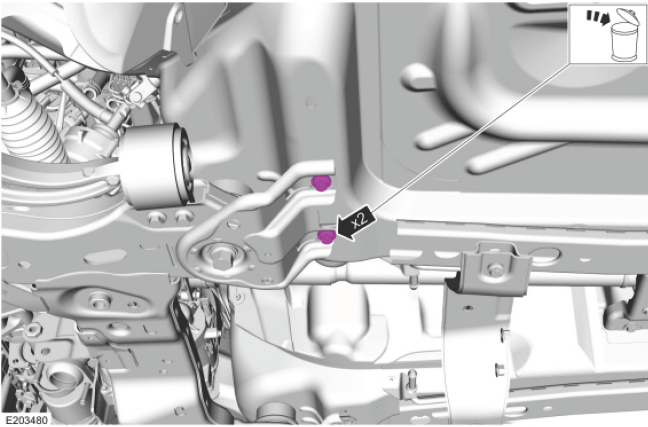
- Remove the Power Transfer Unit (PTU) cooler line mounting bracket bolts.
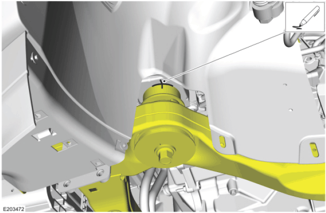
- Index-mark the subframe for reference during installation.
- Index-mark the subframe for reference during installation.
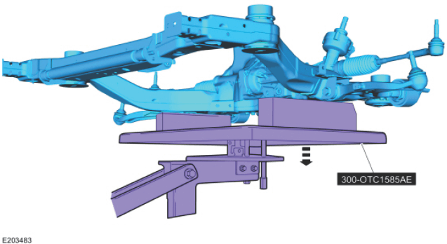
- Position the special tool under the front subframe assembly.
- Use Special Service Tool: 300-OTC1585AE Powertrain Lift.
- Use the General Equipment: Wooden Block
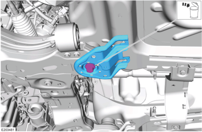
- Remove and discard the front subframe bracket bolts.
- Remove and discard the front subframe rearward bolts and the front subframe brackets.
- Loosen the front subframe forward bolts.
- Lower the subframe to gain access to the steering gear.
- Use Special Service Tool: 300-OTC1585AE Powertrain Lift.
- Use the General Equipment: Wooden Block
-
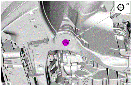
- Remove and discard the steering gear bolts.
- Remove the steering gear from the RH side of the vehicle.
NOTE:
Vehicles equipped with 2.0L GTDI engine.
NOTE:
Vehicles equipped with 3.5L GTDI engine.
NOTE:
Vehicle equipped with 3.5L Ti-VCT engine .
NOTE:
Vehicles equipped with 3.7L Ti-VCT engine .
NOTE:
On both sides
.
CAUTION:
Do not use a hammer to separate the tie rod end from the wheel knuckle or damage to the wheel knuckle may result.
CAUTION:
Use care when installing the tie rod separator or damage to the tie rod end boot may occur.
NOTE:
Use the hex-holding feature to prevent turning of the stud while removing the tie rod end nut.
WARNING:
Do not reuse steering column shaft bolts. This may result in fastener failure and steering column shaft detachment or loss of steering control. Failure to follow this instruction may result in serious injury to vehicle occupant(s).
NOTE:
If equipped.
NOTE:
If equipped.
NOTE:
If equipped.
NOTE:
Front mounting location shown
.
NOTE:
On both sides
.
NOTE:
Rear mounting location shown
.
NOTE:
On both sides
.
NOTE:
On both sides .
NOTE:
On both sides .
NOTE:
On both sides .
NOTE:
The subframe will hang on the forward subframe bolts .
NOTE:
Remove the steering gear from the RH side of the vehicle .