PINPOINT TEST Y : U3003:16 and U3003:17
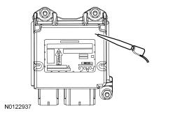
- WARNING: Do not handle, move or change the original horizontal mounting position of the restraints control module (RCM) while the RCM is connected and the ignition switch is ON. Failure to follow this instruction may result in the accidental deployment of the Safety Canopy and cause serious personal injury or death.
- NOTE: Most faults are due to connector and/or wiring concerns. Carry out a thorough inspection and verification before proceeding with the pinpoint test.
- NOTE: Only disconnect or reconnect SRS components when instructed to do so within a pinpoint test step. Failure to follow this instruction may result in incorrect diagnosis of the SRS.
- NOTE: Install new components only when directed to do so in the pinpoint test.
- NOTE: Always make sure the correct SRS component is being installed. Parts released for other vehicles may not be compatible even if they appear physically similar. Check the part number listed in Ford Catalog Advantage™ or equivalent to make sure the correct component is being installed. If an incorrect SRS component is installed, DTCs may set.
- NOTE: The SRS must be fully operational and free of faults before releasing the vehicle to the customer.
- Y1 RETRIEVE ALL CMDTCs IN ALL MODULES
- Ignition ON.
- Using a scan tool, retrieve
ALL CMDTCs.
Is DTC B1317, B1318, B1676, U3003:16 or U3003:17 present in one or more modules AND are any charging system DTCs present in the PCM ?
Yes Go to Pinpoint Test A (System Voltage High) or Go to Pinpoint Test B (System Voltage Low or Battery is Discharged) to diagnose the charging system. No GO to Y2. - Y2 TEST BATTERY CONDITION
- Ignition OFF.
- Carry out the Battery Condition Test. Go to Pinpoint Test A .
Did the battery pass the condition test?
Yes If the battery passed the condition test but required a recharge, Go to Pinpoint Test B to diagnose the charging system. CLEAR all CMDTCs. If the battery passed the condition test and did not require a recharge, GO to Y3. No INSTALL a new battery. REFER to Battery, Mounting and Cables . CLEAR all CMDTCs. - Y3 CHECK THE CHARGING SYSTEM VOLTAGENOTE: Do not allow the engine speed to increase above 2, 000 RPM while performing this step or the generator may self-excite and result in default charging system output voltage. If engine speed goes above 2, 000 RPM, turn the vehicle off and restart the engine before performing this step.
- Measure the voltage of the battery:
- For DTC U3003:17, turn off all accessories and run the engine at 1, 500 Revolutions Per Minute (RPM) for a minimum of 2 minutes while measuring the battery voltage.
- For DTC U3003:16, turn on headlights and HVAC fan on high and run engine at 1, 500 Revolutions Per Minute (RPM) for a minimum of 2 minutes while measuring the battery voltage.
Is the voltage between 13 and 15.2 volts?
Yes For DTC U3003:16, GO to Y4. For DTC U3003:17, GO to Y6. No Go to Pinpoint Test A (System Voltage High) or Go to Pinpoint Test B (System Voltage Low or Battery is Discharged) to diagnose the charging system. CLEAR all CMDTCs. - Y4 CHECK FOR OPEN IGNITION CIRCUIT TO THE MODULE
- Ignition OFF.
- Depower the SRS. Refer to Supplemental Restraint System (SRS) Depowering and Repowering - With Intelligent Access (IA) .
- Disconnect OCSM C3159 .
- For the RCM, measure:
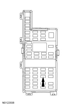
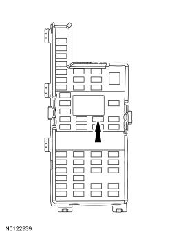
Positive Lead Measurement / Action Negative Lead C310A-19 Fuse 37 (10A)
- For the OCSM, measure:
Positive Lead Measurement / Action Negative Lead C3159-1 Fuse 33 (10A)
Is the resistance less than 1 ohm?
Yes GO to Y5. No REPAIR the circuit as necessary. Refer to CONNECTOR REPAIR PROCEDURES for schematic and connector information. CLEAR all CMDTCs. - Y5 CHECK FOR OPEN GROUND TO THE MODULE
- For the OCSM, measure:
Positive Lead Measurement / Action Negative Lead C3159-4 Ground
Is the resistance less than 1 ohm?
Yes GO to Y6. No For the RCM, VERIFY there is no corrosion between the RCM case and mounting. VERIFY the fasteners are clean and tightened to specification with no corrosion. REPAIR as necessary. Refer to CONNECTOR REPAIR PROCEDURES for schematic and connector information. For the OCSM, REPAIR the circuit. Refer to CONNECTOR REPAIR PROCEDURES for schematic and connector information. CLEAR all CMDTCs. - For the OCSM, measure:
- Y6 CHECK FOR MODULE OPERATION
- Depower the SRS. Refer to Supplemental Restraint System (SRS) Depowering and Repowering - With Intelligent Access (IA) .
- Disconnect the module with the concern:
- Check for the following:
- corrosion
- damaged pins
- pushed-out pins
- Connect the RCM C310A and C310B or OCSM C3159 . Make sure the connector seats correctly and engages the CPA lever/lock.
- Repower the SRS.
Do not prove out the SRS at this time. Refer to Supplemental Restraint System (SRS) Depowering and Repowering - With Intelligent Access (IA) or Refer to Supplemental Restraint System (SRS) Depowering and Repowering - Without Intelligent Access (IA) .
- Operate the system and verify the concern is still present.
Is the concern still present?
Yes CHECK OASIS for any applicable TSBs. If a TSB exists for this concern, discontinue this test and follow TSB instructions. If no TSBs address this concern, and DTC U3003:16 or U3003:17 was present in the RCM, INSTALL a new RCM. REFER to Restraints Control Module (RCM) . If no TSBs address this concern, and DTC U3003:16 or U3003:17 was present in the OCSM, INSTALL a new OCSM. REFER to Occupant Classification System (OCS) Sensor . No The system is operating correctly at this time. The concern may have been caused by a loose or corroded connector. CLEAR all CMDTCs.