Engine - 3.5L Ti-VCT
Overview
Engine
The 3.5L (4V) is a V-6 engine with the following features:
- Dual overhead camshafts
- Four valves per cylinder
- SFI
- Composite upper and lower intake manifolds
- Aluminum cylinder heads
- An aluminum, 60-degree V-cylinder block
- Timing chain driven coolant pump
- Twin independent VCT system
- An electronic ignition system with 6 ignition coils
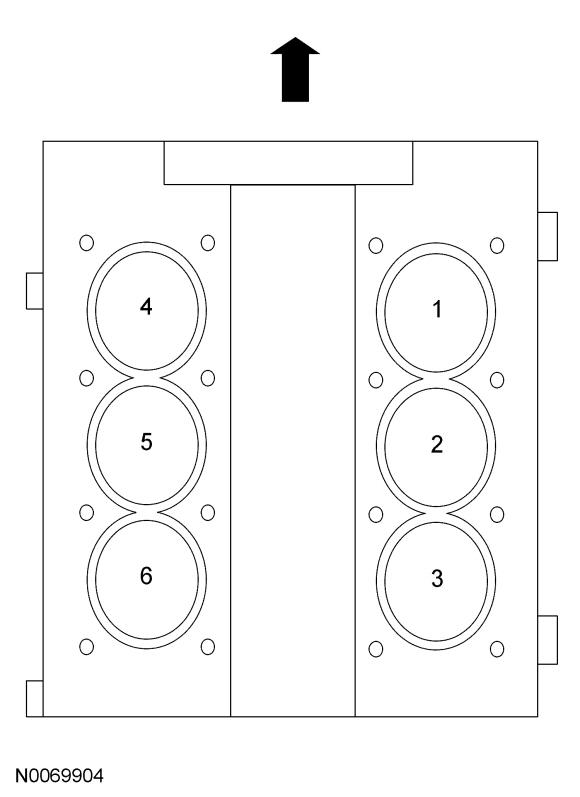
Engine Cylinder Identification
Exhaust Emission Control System
Operation and required maintenance of the exhaust emission control devices used on this engine is covered in the ENGINE CONTROLS - INTRODUCTION (EXCEPT DIESEL & HYBRID) article.
Induction System
The SFI provides the fuel/air mixture needed for combustion in the cylinders. The 6 solenoid operated fuel injectors:
- are mounted between the fuel rail and the intake manifold.
- meter fuel into the air intake stream in accordance with engine demand.
- are positioned so that their tips direct fuel just ahead of the engine intake valves.
Valve Train
The valve train uses DAMB. The camshaft lobes are positioned directly above mechanical buckets which are positioned on top of the valves.
Twin Independent VCT System
The twin independent VCT system allows variable control of the valves that optimizes combustion at full load providing improved power and low speed torque (broadening the torque curve) which enables variable valve overlap which provides better fuel economy and emissions and provides optimized cold start operation with improved exhaust emissions.
PCV System
All engines are equipped with a closed-type PCV system recycling the crankcase vapors to the upper intake manifold.
Lubrication System
The engine lubrication system is of the force-feed type in which oil is supplied under full pressure to the crankshaft, connecting rod bearings, timing chain tensioners, piston oil cooling jets and VCT solenoids. The flow of oil to the valve tappets and valve train is controlled by a restricting orifice located in the cylinder head, front camshaft cap.
Oil Pump
The lubrication system is designed to provide optimum oil flow to critical components of the engine through its entire operating range.
The heart of the system is a positive displacement internal gear oil pump.
Generically, this design is known as a gerotor pump, which operates as follows:
- The oil pump is mounted on the front face of the cylinder block.
- The inner rotor is piloted on the crankshaft post and is driven through flats on the crankshaft.
- System pressure is limited by an integral, internally-vented relief valve which directs the bypassed oil back to the inlet side of the oil pump.
- Oil pump displacement has been selected to provide adequate volume to make sure of correct oil pressure both at hot idle and maximum speed.
- The relief valve calibration protects the system from excessive pressure during high-viscosity conditions.
- The relief valve is designed to provide adequate connecting rod bearing lubrication under high temperature and high-speed conditions.
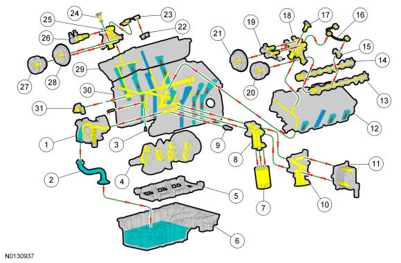
Engine Oil Flow Illustration
| Item | Part Number | Description |
|---|---|---|
| 1 | 6600 6600 | Oil pump |
| 2 | 6622 | Oil pump screen and pickup tube |
| 3 | 6K868 | Piston oil cool valve |
| 4 | 6303 | Crankshaft |
| 5 | 6C364 | Engine main bearing cap support |
| 6 | 6675 | Oil pan |
| 7 | 6714 | Oil filter |
| 8 | 6881 | Oil filter adapter (without oil cooler) |
| 9 | 9278 | EOP sensor |
| 10 | 6881 | Oil filter adapter (with oil cooler) |
| 11 | 6A642 | Oil cooler |
| 12 | 6049 | LH cylinder head |
| 13 | 6250 | Exhaust camshaft |
| 14 | 6250 | Intake camshaft |
| 15 | 6A258 | LH camshaft cap |
| 16 | 6K602 | LH valve train oil feed tube |
| 17 | 6K254 | LH secondary timing chain tensioner |
| 18 | 6B280 | LH camshaft mega cap |
| 19 | 6M280 | LH intake and exhaust camshaft VCT oil control solenoid |
| 20 | 6C525 | LH exhaust camshaft VCT |
| 21 | 6C524 | LH intake camshaft VCT |
| 22 | 6A280 | RH camshaft cap |
| 23 | 6K602 | RH valve train oil feed tube |
| 24 | 6C270 | RH secondary timing chain tensioner |
| 25 | 6B280 | RH camshaft mega cap |
| 26 | 6M280 | RH intake and exhaust camshaft VCT oil control solenoid |
| 27 | 6C525 | RH exhaust camshaft VCT |
| 28 | 6C524 | RH intake camshaft VCT |
| 29 | 6049 | RH cylinder head |
| 30 | 6010 | Cylinder head |
| 31 | 6K254 | Primary timing chain tensioner |
Cooling System
The engine cooling system includes the following:
- Radiator
- Timing chain driven coolant pump
- Electric fan assembly
- Degas bottle (aids in maintaining the correct volume of engine coolant)
- Coolant thermostat
- Coolant hoses
Engine Identification
Engine Identification
For quick identification, refer to the safety certification decal.
The decal is located on the LH front door lock face panel.
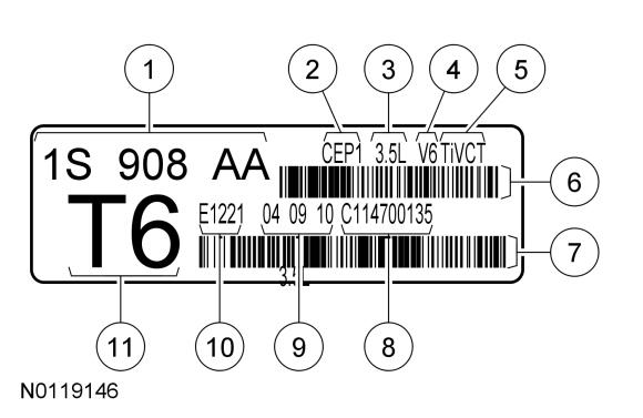
Engine Code Information Label
| Item | Description |
|---|---|
| 1 | Engine part number |
| 2 | Engine plant (Cleveland) |
| 3 | Engine displacement |
| 4 | Engine configuration |
| 5 | Twin independent VCT |
| 6 | Bar code |
| 7 | Bar code |
| 8 | Running number |
| 9 | Engine build date (DDMMYY) |
| 10 | Plant shift line |
| 11 | Derivative code |