Cylinder Head - LH: Installation
NOTE:
During engine repair procedures, cleanliness is extremely important. Any foreign material, including any material created while cleaning gasket surfaces that enters the oil passages, coolant passages or the oil pan, can cause engine failure.
NOTE:
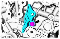
If the cylinder head is replaced, a new secondary timing chain tensioner will need to be installed.
NOTE:
The valve tappets must be installed in their original positions. Coat the valve tappets with clean engine oil prior to installation.
- 1.
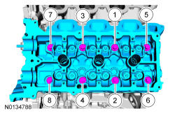
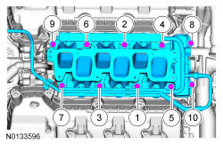
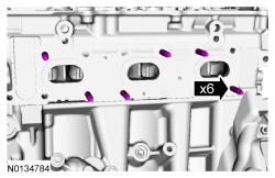
Install a new gasket, the LH cylinder head and 8 new bolts. Tighten the bolts in the sequence shown below in 5 stages:- Stage 1: Tighten to 20 Nm (177 lb-in).
- Stage 2: Tighten to 35 Nm (26 lb-ft).
- Stage 3: Tighten 90 degrees.
- Stage 4: Tighten 90 degrees.
- Stage 5: Tighten 45 degrees.
- 3.
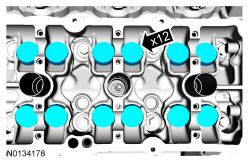
Install the valve tappets.
NOTE:
Coat the valve tappets with clean engine oil prior to installation.
NOTE:
The valve tappets must be installed in their original positions.
- 5.
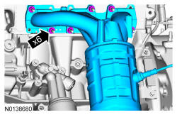
Using new intake manifold and thermostat housing gaskets, install the lower intake manifold and the 10 bolts.- Tighten in the sequence shown to 10 Nm (89 lb-in).
NOTE:
If the engine is repaired or replaced because of upper engine failure, typically including valve or piston damage, check the intake manifold for metal debris. If metal debris is found, install a new intake manifold. Failure to follow these instructions can result in engine damage.
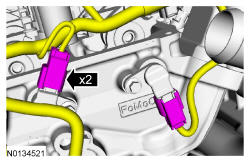
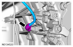
- 7.
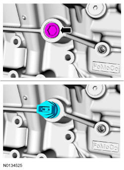
If equipped, install the block heater wiring harness onto the engine.- Stage 1: Tighten the cylinder block drain plug to 10 Nm (89 lb-in) plus an additional 10 Nm (89 lb-in).
- Stage 2: Tighten the block heater to 40 Nm (30 lb-ft).
- 8.
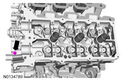
Install the LH cylinder block drain plug.- Tighten to 16 Nm (142 lb-in) plus an additional 180 degrees.
- 10.
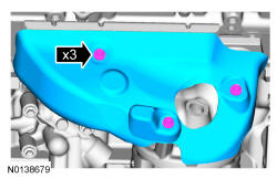
Using a new gasket, install the LH catalytic converter and 3 new lower LH catalytic converter manifold-to-cylinder head nuts. Tighten in 2 stages in the sequence shown below:- Stage 1: Tighten the 3 lower LH catalytic converter manifold-to-cylinder head nuts to 25 Nm (18 lb-ft).
- Stage 2: Install the 3 new upper LH catalytic converter manifold-to-cylinder head nuts and tighten to 25 Nm (18 lb-ft).
- 12.
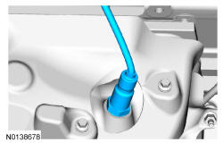
Install the LH HO2S.- Tighten to 48 Nm (35 lb-ft).
NOTE:
Apply anti-seize to the threads of the HO2S prior to installing.
- 14.
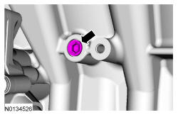
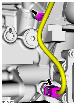
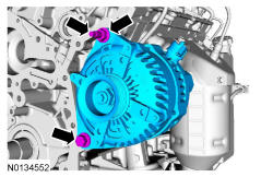
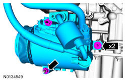
Install the generator stud, generator and the nut and bolt.- Tighten the stud to 8 Nm (71 lb-in).
- Tighten the nut and bolt to 48 Nm (35 lb-ft).

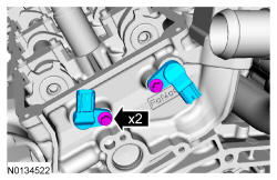
- 20.
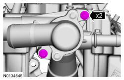
Install the 2 CMP sensors and the 2 bolts.- Tighten to 10 Nm (89 lb-in).
NOTE:
Lubricate the CMP sensor O-ring seal with clean engine oil before installing the CMP sensor.
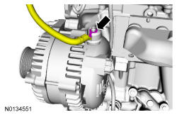
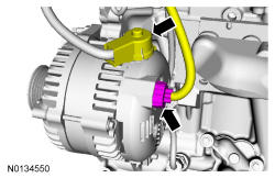
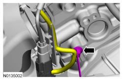
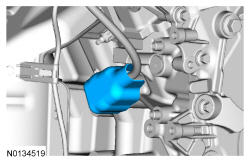
- 22.
If equipped, connect the block heater electrical connector.- Install the block heater wiring harness to the engine.
- 24.
Install the LH camshafts. REFER to Camshaft , Installation.