Engine Front Cover: Installation
- 1.
Clean the engine front cover using a 3M Roloc ® Bristle Disk (2-in white, part number 07528) in a suitable tool turning at the recommended speed of 15, 000 RPM. Thoroughly wash the engine front cover to remove any foreign material, including any abrasive particles created during the cleaning process.
NOTE:
Only use a 3M Roloc ® Bristle Disk (2-in white, part number 07528) to clean the engine front cover. Do not use metal scrapers, wire brushes or any other power abrasive disk to clean front cover.
- 2.
Clean the sealing surfaces of the cylinder heads, the cylinder block and the oil pan in the following sequence.- Remove any large deposits of silicone or gasket material.
- Apply Motorcraft ®Silicone Gasket Remover and allow to set for several minutes.
- Remove the Motorcraft ®Silicone Gasket Remover. A second application of Motorcraft ®Silicone Gasket Remover may be required if residual traces of silicone or gasket material remain.
- Apply Motorcraft ® Metal Surface Prep to remove any remaining traces of oil or coolant and to prepare the surfaces to bond. Do not attempt to make the metal shiny. Some staining of the metal surfaces is normal.
NOTE:
Do not use wire brushes, power abrasive discs or 3M Roloc ® Bristle Disk (2-in white part number 07528) to clean the sealing surfaces of engine block, cylinder heads, and oil pan. These tools can cause contamination that will cause premature engine failure. Remove all traces of the gasket.
NOTE:
Place clean, lint-free shop towels over exposed engine cavities. Carefully remove the towels so foreign material is not dropped into the engine. Any foreign material (including any material created while cleaning gasket surfaces) that enters the oil passages or the oil pan, may cause engine failure.
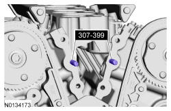
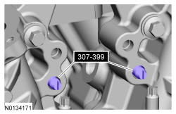
- 3.
Install 307-399.
NOTE:
Make sure the 2 locating dowel pins are seated correctly in the cylinder block.
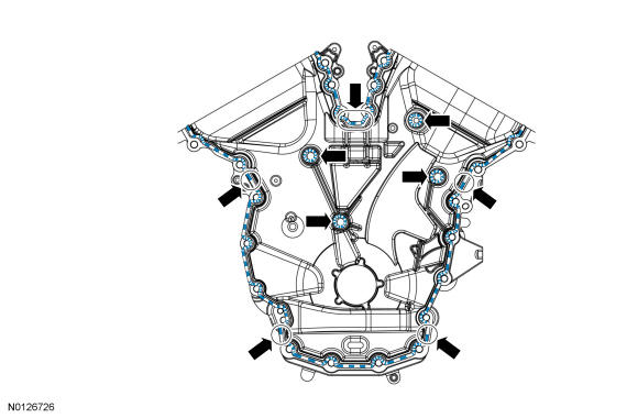
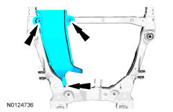
- 4.
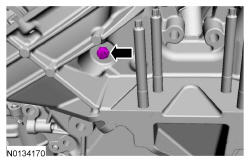
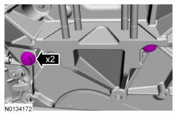
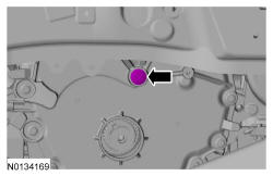
Apply a 3 mm (0.1181 in) bead of Motorcraft ® High Performance Engine RTV Silicone to the sealing surface of the front cover.- Apply a 5.5 mm (0.22 in) bead of Motorcraft ® High Performance Engine RTV Silicone to the oil pan-to-cylinder block joint and the cylinder head-to-cylinder block joint areas of the engine front cover in 5 places as indicated.
NOTE:
The engine front cover and bolts 7, 8, 15, 17, 18, 21 and 22 must be installed within 4 minutes of the initial sealant application. The remainder of the engine front cover bolts must be installed and tightened within 35 minutes of the initial sealant application. If the time limits are exceeded, the sealant must be removed, the sealing area cleaned and sealant reapplied. To clean the sealing area, use Motorcraft ®Silicone Gasket Remover and Motorcraft ® Metal Surface Prep. Failure to follow this procedure can cause future oil leakage.
NOTE:
Failure to use Motorcraft ® High Performance Engine RTV Silicone may cause the engine oil to foam excessively and result in serious engine damage.
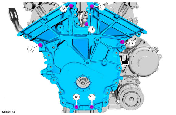
- 5.
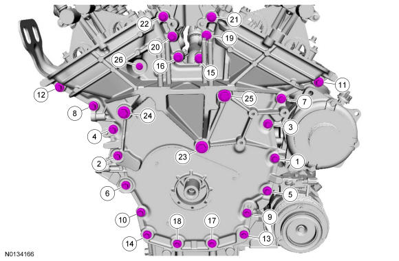
Install the engine front cover and bolts 7, 8, 15, 17, 18, 21 and 22.- Tighten in sequence shown to 3 Nm (27 lb-in).
NOTE:
Make sure the 2 locating dowel pins are seated correctly in the cylinder block.
- 9.
Install the lower M10 bolt. Do not tighten at this time.
NOTE:
It may be necessary to use the floor jack and lower the engine slightly to gain enough access to install the bolt.
- 10.
Install the remaining engine front cover bolts. Tighten all of the engine front cover bolts in the sequence shown in 7 stages.- Stage 1: Tighten bolts 1 thru 22 to 10 Nm (89 lb-in).
- Stage 2: Tighten bolts 23 thru 25 to 15 Nm (133 lb-in).
- Stage 3: Tighten bolt 26 to 10 Nm (89 lb-in).
- Stage 4: Loosen bolt 26 one full turn.
- Stage 5: Tighten bolts 23 thru 25 to 30 Nm (22 lb-ft) plus an additional 90 degrees.
- Stage 6: Tighten bolts 1 thru 22 to 20 Nm (177 lb-in) plus an additional 45 degrees.
- Stage 7: Tighten bolt 26 to 10 Nm (89 lb-in) plus an additional 45 degrees.
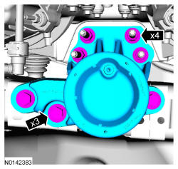
- 11.
Install the engine mount, 4 engine mount nuts and 3 engine mount bolts hand tight.- Tighten the 3 engine mount bolts to 90 Nm (66 lb-ft).
- Tighten the 4 engine mount nuts to 63 Nm (46 lb-ft).
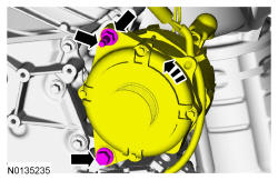
- 12.
Position the generator and install the stud and nut.- Tighten the stud to 8 Nm (71 lb-in).
- Tighten the nut to 47 Nm (35 lb-ft).
- Tighten the bolt to 47 Nm (35 lb-ft).
- 13.
Install the LH and RH valve covers. Refer to Valve Cover - LH and Refer to Valve Cover - RH .
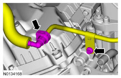
- 14.
Install the fuel tube-to-engine front cover bolt.- Tighten the bolt to 10 Nm (89 lb-in).
- Connect the fuel supply tube to the fuel rail supply tube. REFER to Fuel System General Information .
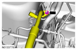
- 15.
Using a new O-ring seal, connect the A/C pressure tube fitting and install the nut.- Tighten to 8 Nm (71 lb-in).

- 17.
Install degas bottle. REFER to Engine Cooling .
- 18.
If equipped, attach the engine block heater harness to the radiator support, the A/C suction tube and the engine wiring harness.
- 19.
Install the accessory drive belt tensioner. REFER to Accessory Drive .
- 20.
Install the crankshaft front seal. Refer to Crankshaft Front Seal .
- 22.
Install the RH fender splash shield. REFER to Front End Body Panels .
- 24.
Fill the cooling system. REFER to Engine Cooling .
- 25.
Connect the battery ground cable. REFER to Battery, Mounting and Cables .
- 26.
Evacuate and recharge the A/C system. REFER to Climate Control EMTC .