Valve Cover - LH: Installation
- 1.
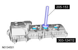
Using 303-1247/2 and 205-153 T80T-4000-W install the new spark plug tube seal(s).
NOTE:
Installation of new seals is only required if damaged seals were removed.
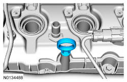
- 2.
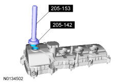
Using 205-142 T80T-4000-J and 205-153 T80T-4000-W install the new VCT seal(s).
NOTE:
Installation of new seals is only required if damaged seals were removed.
- 3.
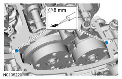
Apply an 8 mm (0.315 in) bead of Motorcraft ® High Performance Engine RTV Silicone to the engine front cover-to-Left Hand (LH) cylinder head joints.
NOTE:
If the valve cover is not installed and the fasteners tightened within 4 minutes, the sealant must be removed and the sealing area cleaned. To clean the sealing area, use Motorcraft ®Silicone Gasket Remover and Motorcraft ® Metal Surface Prep. Failure to follow this procedure can cause future oil leakage.
NOTE:
Failure to use Motorcraft ® High Performance Engine RTV Silicone may cause the engine oil to foam excessively and result in serious engine damage.
- 4.
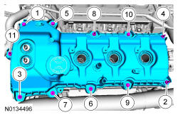
Using a new gasket, install the LH valve cover and tighten the 4 bolts and 7 stud bolts.- Tighten in the sequence shown to 10 Nm (89 lb-in).
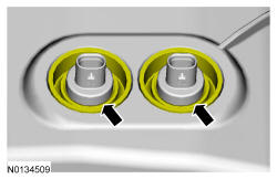
- 5.
Ensure the VCT seals in the valve cover are below the top of the connector (flat portion) on the VCT oil control valve otherwise the interface may leak.
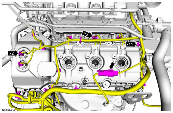
- 6.
Install the engine wiring harness to the LH valve cover.- Position the wiring harness and attach the 11 wiring harness retainers to the LH valve cover and stud bolts.
- Connect the 3 fuel injector electrical connectors.
- Connect and attach the LH HO2S electrical connector.
- Connect the 2 VCT oil control solenoid electrical connectors.
- 7.
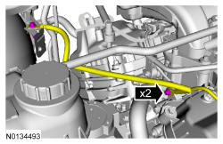
Position the ground wires to the engine front cover and the RH strut tower and install the 2 bolts.- Tighten to 10 Nm (89 lb-in).
- 9.
Install the LH ignition coils. Refer to IGNITION COIL-ON-PLUG -- LH .
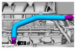
- 10.
Install the crankcase vent tube. REFER to Fuel System General Information .