Disassembly And Assembly: Engine: Disassembly
WARNING:
Before beginning any service procedure in this article, refer to Safety Warnings in SERVICE INFORMATION
.
NOTE:
During engine repair procedures, cleanliness is extremely important. Any foreign material, including any material created while cleaning gasket surfaces that enters the oil passages, coolant passages or the oil pan, can cause engine failure.
NOTE:
If the cylinder head(s) is replaced, a new secondary timing chain tensioner will need to be installed.
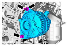
- 3.
Mount the engine on a suitable engine stand.
NOTE:
Install the engine stand bolts into the cylinder block only. Do not install the bolts into the oil pan.
- 5.
If equipped, disconnect the block heater electrical connector.- Detach all of the engine block heater harness retainers and remove the harness.
- 8.
Using a three leg puller, remove the crankshaft pulley.
NOTE:
Use a three leg puller (such as Matco Tools ® MST9740D, or equivalent).
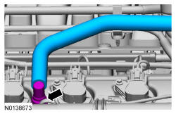
- 10.
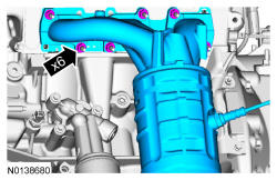
Remove the crankcase vent tube. REFER to Fuel System General Information .
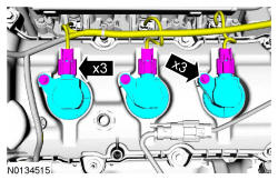
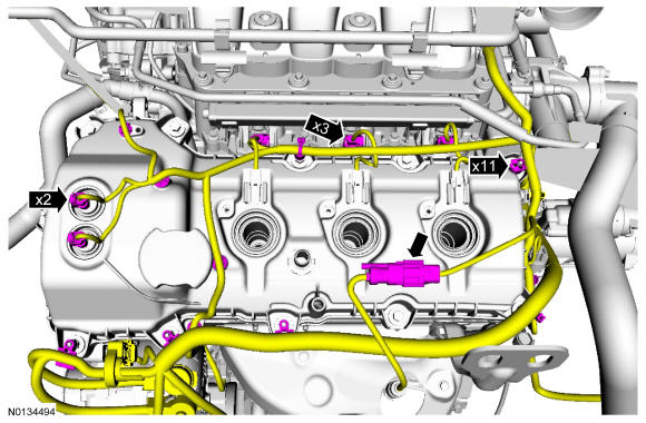
- 11.
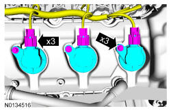
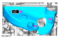
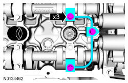
Disconnect the 3 LH coil-on-plug electrical connectors and remove the 3 bolts and the 3 LH coil-on- plugs.- Inspect the coil seals for rips, nicks or tears. Remove and discard any damaged coil seals.
NOTE:
When removing the ignition coil-on-plugs, a slight twisting motion will break the seal and ease removal.
- 14.
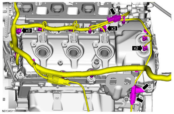
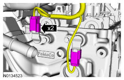
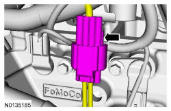
Remove the engine wiring harness from the LH valve cover.- Disconnect the 2 VCT oil control solenoid electrical connectors.
- Detach and disconnect the LH HO2S electrical connector.
- Disconnect the 3 fuel injector electrical connectors.
- Detach the 11 wiring harness retainers from the LH valve cover and stud bolts and position the harness aside.
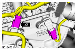
- 17.
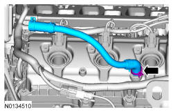
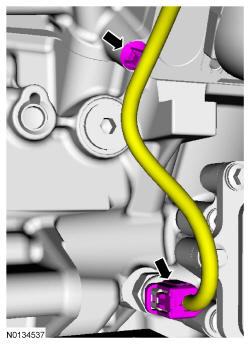
Disconnect the EVAP canister purge valve and throttle body electrical connectors.- Detach the wiring harness pin-type retainer.
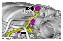
- 18.
Disconnect the EVAP vapor tube from the EVAP canister purge valve. REFER to Fuel System General Information .- Detach the EVAP vapor tube from the 2 retainers.
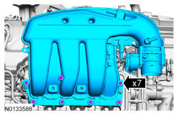
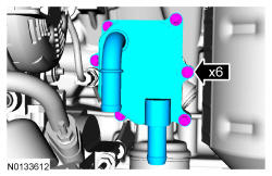
- 22.
Remove the 7 bolts and the upper intake manifold.- Remove and discard the gasket.
- Clean and inspect all of the sealing surfaces of the upper and lower intake manifold.
- 23.
Disconnect the 3 RH coil-on-plug electrical connectors and remove the 3 bolts and the 3 RH coil-on-plugs.- Inspect the coil seals for rips, nicks or tears. Remove and discard any damaged coil seals.
NOTE:
When removing the ignition coil-on-plugs, a slight twisting motion will break the seal and ease removal.
- 25.
Remove the engine wiring harness from the RH valve cover.- Disconnect the 2 VCT oil control solenoid electrical connectors.
- Detach and disconnect the RH CMS electrical connector.
- Disconnect the 3 fuel injector electrical connectors.
- Disconnect the CHT sensor wiring harness jumper electrical connector.
- Detach the 9 wiring harness retainers from the RH valve cover and stud bolts and position the harness aside.
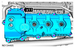
- 26.
Loosen the 4 bolts and 7 stud bolts and remove the LH valve cover.- Discard the gasket.
NOTE:
The plastic electrical connector on the VCT oil control solenoid will rotate approximately 12 degrees inside the steel housing, which is normal.
NOTE:
If the VCT solenoid seal sticks to the VCT oil control solenoid, then carefully wiggle the valve cover until the bond breaks free.
NOTE:
While removing the valve cover do not apply excessive force to the VCT oil control solenoid or damage may occur.
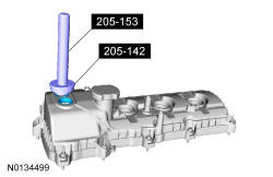
- 27.
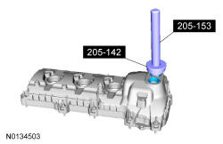
Inspect the 2 VCT solenoid seals. Remove any damaged seals.- Using 205-142 T80T-4000-J and 205-153 T80T-4000-W remove and discard the damaged seal(s).
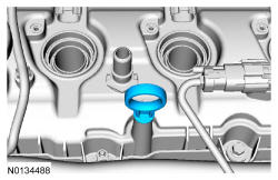
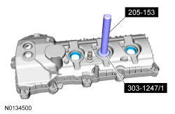
- 28.
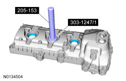
Inspect the spark plug tube seals. Remove any damaged seals.- Using 303-1247/1 and 205-153 T80T-4000-W remove and discard the damaged seal(s).
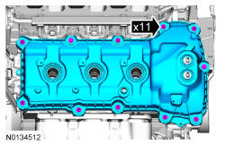
- 29.
Loosen the 3 bolts and 8 stud bolts. Remove the RH valve cover. Discard the gasket.
NOTE:
The plastic electrical connector on the VCT oil control solenoid will rotate approximately 12 degrees inside the steel housing, which is normal.
NOTE:
If the VCT solenoid seal sticks to the VCT oil control solenoid, then carefully wiggle the valve cover until the bond breaks free.
NOTE:
While removing the valve cover do not apply excessive force to the VCT oil control solenoid or damage may occur.
- 30.
Inspect the 2 VCT solenoid seals. Remove any damaged seals.- Using 205-142 T80T-4000-J and 205-153 T80T-4000-W remove and discard the damaged seal(s).
- 31.
Inspect the spark plug tube seals. Remove any damaged seals.- Using 303-1247/1 and 205-153 T80T-4000-W remove and discard the damaged seal(s).
- 32.
Clean the valve covers, cylinder heads and engine front cover sealing surfaces with metal surface prep.

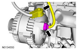
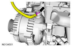
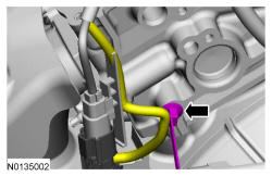
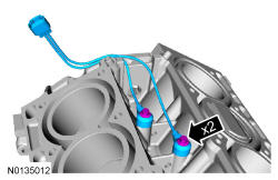
- 45.
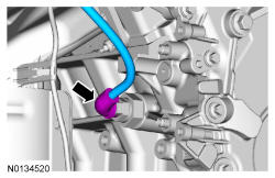
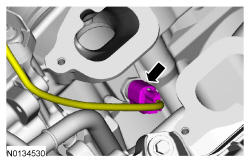
Disconnect the EOP switch electrical connector and the wiring harness pin-type retainer.- Remove the wiring harness from the engine.
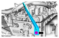
- 48.
Remove the LH HO2S.
NOTE:
If necessary, lubricate the Left Hand (LH) HO2S with penetrating and lock lubricant to assist in removal.
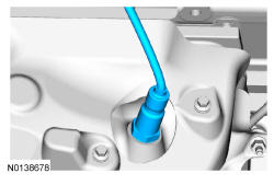
- 51.
Clean and inspect the catalytic converter flange. REFER to Engine System General Information .
- 54.
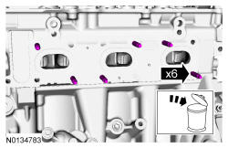
If equipped with FWD, remove the 6 nuts and the RH catalytic converter manifold.- Discard the nuts and RH catalytic converter manifold gasket.
- 55.
Clean and inspect the RH catalytic converter manifold. REFER to Engine System General Information .
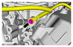
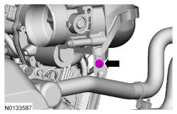
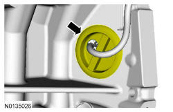
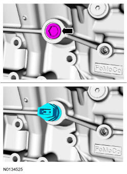
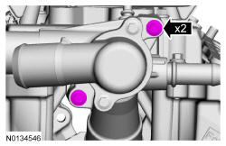
- 57.
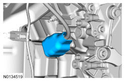
Remove the RH cylinder block drain plug or, if equipped, the block heater. Allow coolant to drain from the cylinder block.
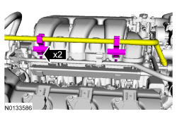
- 63.
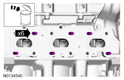
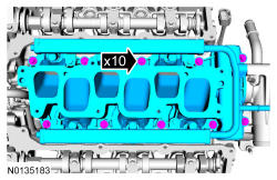
Remove the 10 bolts and the lower intake manifold.- Remove and discard the intake manifold and thermostat housing gaskets.
- Clean and inspect all sealing surfaces.
NOTE:
If the engine is repaired or replaced because of upper engine failure, typically including valve or piston damage, check the intake manifold for metal debris. If metal debris is found, install a new intake manifold. Failure to follow these instructions can result in engine damage.
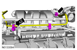
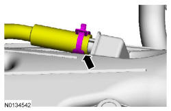
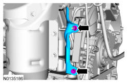
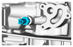
- 64.
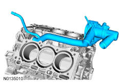
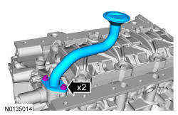
Remove the coolant inlet tube and thermostat assembly.- Remove and discard the O-ring seal.
NOTE:
Cylinder heads removed for clarity.
- 66.
If equipped, remove the 6 bolts and the oil cooler.- Discard the oil cooler and gasket.
NOTE:
A new oil cooler must be installed or severe damage to the engine can occur.
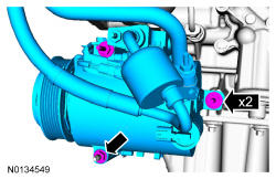
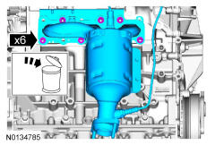
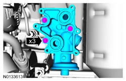
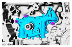
- 67.
Remove the 3 bolts and the oil filter adapter.- Discard the gasket.
NOTE:
Oil filter adapter with oil cooler shown, oil filter adapter without oil cooler similar.
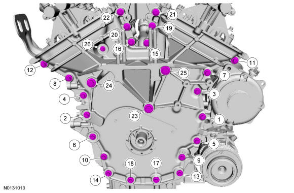
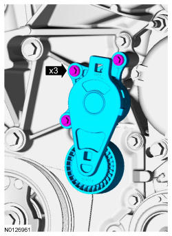
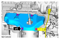
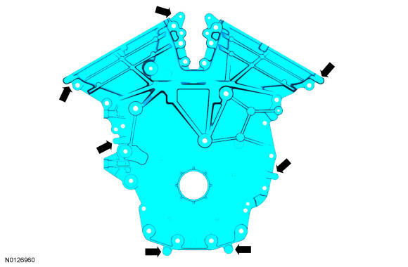
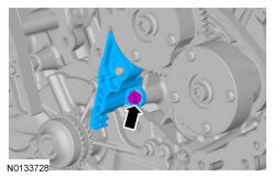
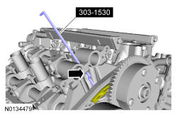
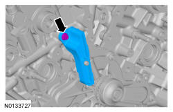
- 70.
Using a suitable pry tool, locate the 7 pry pads shown and pry the engine front cover loose and remove.
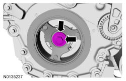
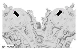
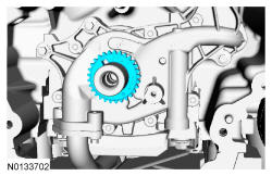
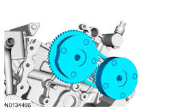
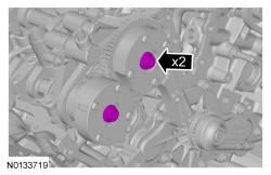
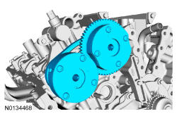
- 71.
Rotate the crankshaft clockwise and align the timing marks on the intake VCT assemblies as shown.
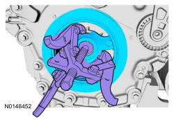
- 73.
Install the Camshaft Holding Tool onto the flats of the LH camshafts.
NOTE:
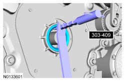
The Camshaft Holding Tool will hold the camshafts in the TDC position.
- 75.
Install the Camshaft Holding Tool onto the flats of the RH camshafts.
NOTE:
The Camshaft Holding Tool will hold the camshafts in the TDC position.
- 76.
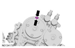
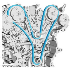
Mark the timing chain link that aligns with the timing mark on the LH intake VCT assembly as shown.
NOTE:
The following 3 steps are for primary timing chains that the colored links are not visible.
- 77.
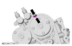
Mark the timing chain link that aligns with the timing mark on the RH intake VCT assembly as shown.
- 78.
Mark the 2 timing chain links that align with the timing mark on the crankshaft sprocket as shown.
NOTE:
The crankshaft sprocket timing mark should be between the 2 colored links.
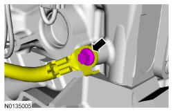
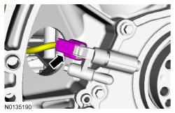
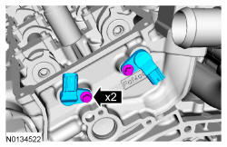
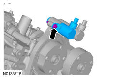
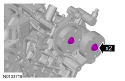
- 82.
Remove the bolt and the LH intake VCT oil control solenoid.
NOTE:
Keep the VCT oil control solenoid clean of dirt and debris.
NOTE:
A slight twisting motion will aid in the removal of the VCT oil control solenoid.
NOTE:
Removal of the VCT oil control solenoid will aid in the removal of the primary timing chain.
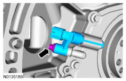
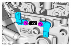
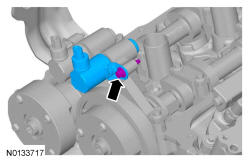
- 83.
Remove the bolt and the RH intake VCT oil control solenoid.
NOTE:
Keep the VCT oil control solenoid clean of dirt and debris.
NOTE:
A slight twisting motion will aid in the removal of the VCT oil control solenoid.
NOTE:
Removal of the VCT oil control solenoid will aid in the removal of the primary timing chain.
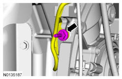
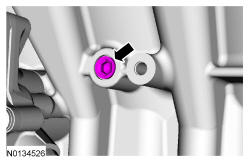
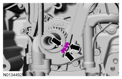
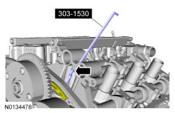
- 86.
Remove the bolt and the upper LH primary timing chain guide
NOTE:
Do not use power tools to remove the bolt or damage to the LH primary timing chain guide may occur.
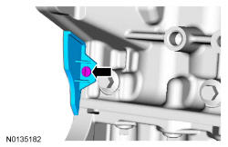
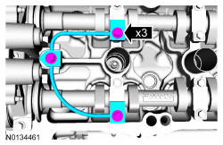
- 87.
Compress the LH secondary timing chain tensioner and install the Secondary Chain Hold Down in the hole on the rear of the secondary timing chain tensioner guide and let it hold against the mega cap to retain the tensioner in the collapsed position.
NOTE:
The Secondary Chain Hold Down is inserted through a hole in the top of the mega cap.
NOTE:
The 2 VCT oil control solenoids are removed for clarity.
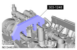
- 90.
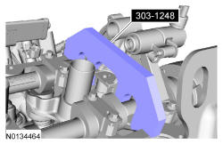
Remove 303-1248 from the LH camshafts.
NOTE:
When the 303-1248 is removed, valve spring pressure may rotate the LH camshafts approximately 3 degrees to a neutral position.
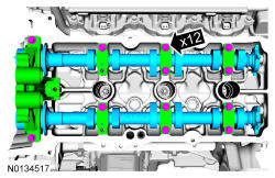
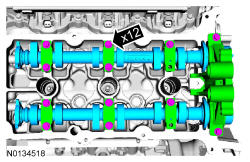
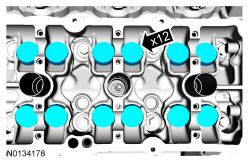
- 91.
Remove the 12 bolts, 6 camshaft caps, mega cap and the LH camshafts.
NOTE:
Mark the exhaust and intake camshafts for installation into their original locations.
NOTE:
Cylinder head camshaft bearing caps are numbered to verify that they are assembled in their original positions.
- 92.
Compress the RH secondary timing chain tensioner and install the Secondary Chain Hold Down in the hole on the rear of the secondary timing chain tensioner guide and let it hold against the mega cap to retain the tensioner in the collapsed position.
NOTE:
The Secondary Chain Hold Down is inserted through a hole in the top of the mega cap.
NOTE:
The 2 VCT oil control solenoids are removed for clarity.
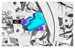
- 95.
Remove the bolt and the RH primary timing chain guide.
NOTE:
Do not use power tools to remove the bolt or damage to the RH primary timing chain guide may occur.
- 96.
NOTE:
When the 303-1248 is removed, valve spring pressure may rotate the RH camshafts approximately 3 degrees to a neutral position.
NOTE:
Remove 303-1248 from the RH camshafts.
- 97.
Remove the 12 bolts, 6 camshaft caps, mega cap and the RH camshafts.
NOTE:
Mark the exhaust and intake camshafts for installation into their original locations.
NOTE:
Cylinder head camshaft bearing caps are numbered to verify that they are assembled in their original positions.
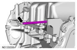
NOTE:
Index-mark the location of the bracket on the cylinder head for installation. Remove the bolt and the upper intake manifold bracket.
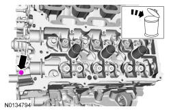
- 100.
Remove the valve tappets from the cylinder heads.
NOTE:
LH shown, RH similar.
NOTE:
If the components are to be reinstalled, they must be installed in the same positions. Mark the components for installation into their original locations.
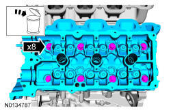
- 102.
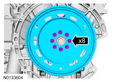
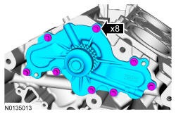
Remove and discard the 8 bolts from each cylinder head. Remove the cylinder heads. Discard the cylinder head gaskets.
NOTE:
LH shown, RH similar.
NOTE:
The cylinder head bolts must be discarded and new bolts must be installed. They are tighten-to-yield designed and cannot be reused.
NOTE:
Aluminum surfaces are soft and can be scratched easily. Never place the cylinder head gasket surface, unprotected, on a bench surface.
NOTE:
Place clean, lint-free shop towels over exposed engine cavities. Carefully remove the towels so foreign material is not dropped into the engine. Any foreign material (including any material created while cleaning gasket surfaces) that enters the oil passages or the oil pan, may cause engine failure.
- 103.
Apply silicone gasket remover, following package directions, and allow to set for several minutes. Apply metal surface prep, following package directions, to remove any remaining traces of oil or coolant and to prepare the surfaces to bond with the new gasket.- Remove the silicone gasket remover with a plastic scraper. A second application of silicone gasket remover may be required if residual traces of silicone or gasket material remain.
- Do not attempt to make the metal shiny. Some staining of the metal surfaces is normal. Make sure the 2 locating dowel pins are seated correctly in the cylinder block.
NOTE:
If there is no residual gasket material present, metal surface prep can be used to clean and prepare the surfaces. Clean the cylinder head-to-cylinder block mating surfaces of both the cylinder heads and the cylinder block in the following sequence. Remove any large deposits of silicone or gasket material with a plastic scraper.
NOTE:
Observe all warnings or cautions and follow all application directions contained on the packaging of the silicone gasket remover and the metal surface prep.
NOTE:
Do not use metal scrapers, wire brushes, power abrasive discs or other abrasive means to clean the sealing surfaces. These tools cause scratches and gouges that make leak paths. Use a plastic scraping tool to remove all traces of the head gasket.
- 104.
Support the cylinder head on a bench with the head gasket side up. Check the cylinder head distortion and the cylinder block distortion.
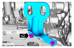
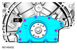
- 111.
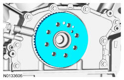
Remove the 8 bolts and the crankshaft rear seal retainer plate.- Discard the plate and seal assembly.
- 112.
Clean the engine front cover and oil pan using a 3M Roloc ® Bristle Disk (2 inch, white, part number 07528) in a suitable tool turning at the recommended speed of 15, 000 RPM. Thoroughly wash the engine front cover and oil pan to remove any foreign material, including any abrasive particles created during the cleaning process.
NOTE:
Only use a 3M™ Roloc ® Bristle Disk (2-in white, part number 07528) to clean the engine front cover and oil pan. Do not use metal scrapers, wire brushes or any other power abrasive disk to clean the engine front cover and oil pan. These tools cause scratches and gouges that make leak paths.
- 113.
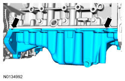
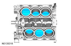
Before removing the pistons, inspect the top of the cylinder bores. If necessary, remove the ridge or carbon deposits from each cylinder using an abrasive pad or equivalent, following manufacturer's instructions.
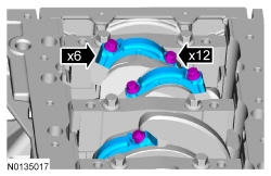
- 114.
Remove the bolts in the sequence shown. Remove the main bearing cap support brace. Discard the bolts.
NOTE:
The main bearing cap support brace bolts must be discarded and new bolts must be installed. They are a tighten-to-yield design and cannot be reused.
- 115.
Remove the connecting rod cap bolts and cap.
NOTE:
Clearly mark the position and orientation of the connecting rods, connecting rod caps and connecting rod bearings for reassembly.
NOTE:
The connecting rod cap bolts are a torque-to-yield design. The original connecting rod cap bolts will be used when measuring the connecting rod large end bore during assembly. The connecting rod cap bolts will be discarded after measurement.
- 116.
Remove the piston/rod assembly from the engine block.
NOTE:
Do not scratch the cylinder walls or crankshaft journals with the connecting rod.
- 117.
Repeat the previous 2 steps until all the piston/rod assemblies are removed from the engine block.
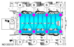
- 118.
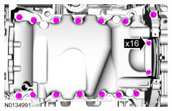
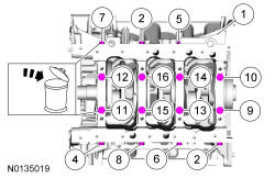
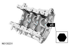
Remove the 8 main bearing cap side bolts and the 8 main bearing cap bolts in the sequence shown. Discard the bolts.
NOTE:
Clearly mark the position and orientation of the main bearing caps for reassembly.
NOTE:
The 8 main bearing cap side bolts and the 8 main bearing cap bolts must be discarded and new bolts must be installed. They are a tighten-to-yield design and cannot be reused.
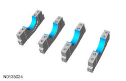
- 119.
Remove the 4 main bearing caps.
NOTE:
Note the position of the thrust washer on the outside of the No. 4 rear main bearing cap.
NOTE:
If the main bearings are being reused, mark them for correct position and orientation for reassembly.
- 120.
Remove the lower crankshaft thrust washer from the back side of the No. 4 rear main bearing cap.
- 121.
Remove the 4 crankshaft main bearings from the main bearing caps.
NOTE:
If the main bearings are being reused, mark them for correct position and orientation for reassembly.
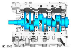
- 122.
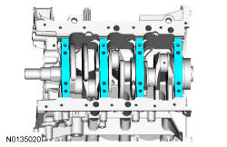
Remove the crankshaft.
NOTE:
Note the position of the 2 thrust washers on the inside and outside of the rear main bearing bulkhead.
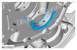
- 123.
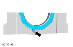
Remove the 2 crankshaft thrust bearings from the rear main bearing bulkhead.
NOTE:
Inside shown, outside similar.
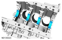
- 124.
Remove the 4 crankshaft main bearings from the cylinder block.
NOTE:
If the main bearings are being reused, mark them for correct position and orientation for reassembly.
- 127.
Clean the sealing surfaces of the cylinder block in the following sequence.- Remove any large deposits of silicone or gasket material.
- Apply silicone gasket remover and allow to set for several minutes.
- Remove the silicone gasket remover.
- A second application of silicone gasket remover may be required if residual traces of silicone or gasket material remain.
- Apply metal surface prep to remove any remaining traces of oil or coolant and to prepare the surfaces to bond. Do not attempt to make the metal shiny. Some staining of the metal surfaces is normal.
NOTE:
Do not use wire brushes, power abrasive discs or 3M Roloc ® Bristle Disk (2-in white part number 07528) to clean the sealing surfaces. These tools cause scratches and gouges that make leak paths. They also cause contamination that will cause premature engine failure. Remove all traces of the gasket.
NOTE:
Place clean, lint-free shop towels over exposed engine cavities. Carefully remove the towels so foreign material is not dropped into the engine. Any foreign material (including any material created while cleaning gasket surfaces) that enters the oil passages or the oil pan, may cause engine failure.