Disassembly And Assembly: Engine: Assembly
NOTE:
During engine repair procedures, cleanliness is extremely important. Any foreign material, including any material created while cleaning gasket surfaces that enters the oil passages, coolant passages or the oil pan, may cause engine failure.
NOTE:
Assembly of the engine requires various inspections/measurements of the engine components (engine block, crankshaft, connecting rods and pistons). These inspections/measurements will aid in determining if the engine components will require replacement. REFER to Engine System General Information
.
NOTE:
The Wheel Hub Bearing Cup Installer is used to install the VCT solenoid seals.
NOTE:
Refer to exploded view(s) and any Warnings, Notices, Notes, Materials, Specifications, and Special Tools. Items in the exploded views may not be listed in order of removal.
- 2.
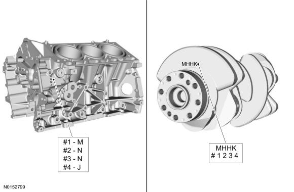
Select the crankshaft main bearings for each crankshaft journal.- Record the code that is on the cylinder block face.
- Record the code that is on the crankshaft flange.
- The first letter is for main No. 1 and the next letters are for mains 2, 3 and 4.
NOTE:
The #1 main bearing is at the front of the engine block.
NOTE:
This step is for selecting the correct main bearings.
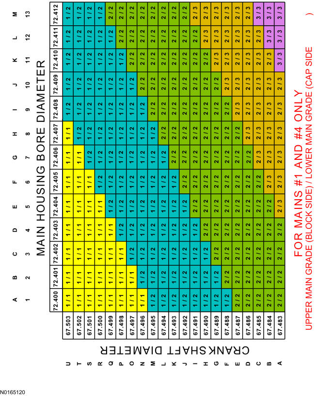
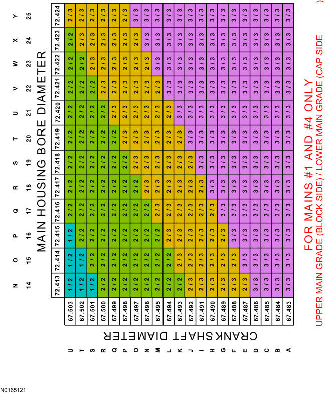
- 3.
Using the data recorded earlier and the Bearing Select Fit Chart, Standard Bearings, determine the required bearing grade for main bearings 1 and 4.- Read the first letter of the engine block main bearing code and the first letter of the crankshaft main bearing code.
- Read down the column below the engine block main bearing code letter and across the row next to the crankshaft main bearing code letter, until the 2 intersect. This is the required bearing grade(s) for the No. 1 crankshaft main bearing.
- As an example, if the engine block code letter is "M" and the crankshaft code letter is "M", the correct bearing grade for this main bearing is a "2" for the upper bearing and a "2" for the lower bearing.
- Repeat the above steps using the fourth letter of the block and crankshaft codes to select the No. 4 bearing.
NOTE:
This chart is for selecting main bearings 1 and 4 only.
NOTE:
This chart is continued in the next step.
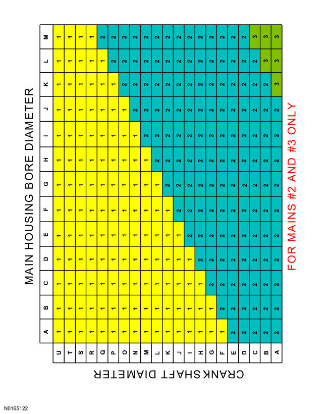
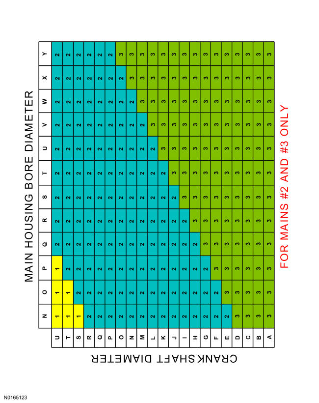
- 5.
Using the data recorded earlier and the Bearing Select Fit Chart, Standard Bearings, determine the required bearing grade for main bearings 2 and 3.- Read the second letter of the engine block main bearing code and the second letter of the crankshaft main bearing code.
- Read down the column below the engine block main bearing code letter and across the row next to the crankshaft main bearing code letter, until the 2 intersect. This is the required bearing grade for the No. 2 crankshaft main bearing.
- As an example, if the engine block code letter is "N" and the crankshaft code letter is "H", the correct bearing grade for this main bearing is "2".
- Repeat the above steps using the third letter of the block and crankshaft codes to select the No. 3.
NOTE:
This chart is for selecting main bearings 2 and 3 only.
NOTE:
This chart is continued in the next step.
- 7.
Using the original connecting rod cap bolts, install the connecting rod caps and bolts. Tighten the bolts in 3 stages.- Stage 1: Tighten to 23 Nm (17 lb-ft).
- Stage 2: Tighten to 43 Nm (32 lb-ft).
- Stage 3: Tighten an additional 90 degrees.
NOTE:
The rod cap installation must keep the same orientation as marked during disassembly or engine damage may occur.
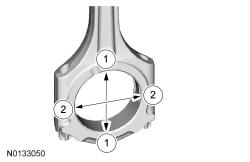
- 8.
Measure the connecting rod large end bore in 2 directions.- Remove the bolts and the rod cap.
- Discard the connecting rod cap bolts.
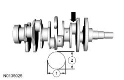
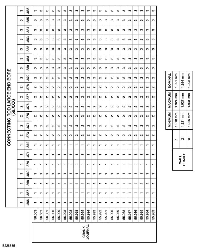
- 10.
Using the chart, select the correct connecting rod bearings for each crankshaft connecting rod journal.
- 11.
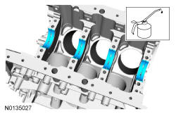
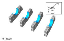
Lubricate the upper crankshaft main bearings with clean engine oil and install the 4 crankshaft main bearings in the cylinder block.
NOTE:
Before assembling the cylinder block, all sealing surfaces must be free of chips, dirt, paint and foreign material. Also, make sure the coolant and oil passages are clear.
- 12.
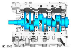
Install the crankshaft onto the upper main bearings.
NOTE:
Lubricate the thrust surfaces of the crankshaft with clean engine oil.
NOTE:
Do not install the upper thrust bearings until the crankshaft is installed.
- 13.
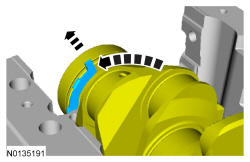
Push the crankshaft rearward and install the rear crankshaft upper thrust washer at the back of the No. 4 rear bulkhead.
NOTE:
Make sure the side of the thrust washer, with the wide oil grooves, faces the crankshaft thrust surface.
- 14.
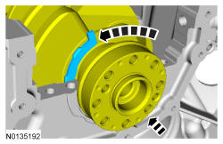
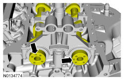
Push the crankshaft forward and install the front crankshaft upper thrust washer at the front of the No. 4 rear bulkhead.
NOTE:
Make sure the side of the thrust washer, with the wide oil grooves, faces the crankshaft thrust surface.
- 15.
Lubricate the crankshaft lower main bearings with clean engine oil and install them into the main bearing caps. Visually check seating and squareness of the bearings to make sure of proper seating in caps.
- 16.
Position the No. 1, No. 2 and No. 3 main bearing caps on the cylinder block and, keeping the caps as square as possible, alternately draw the caps down evenly using the new bolts until the main bearing caps are seated.
- 17.
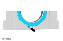
Install the lower crankshaft thrust washer to the back side of the No. 4 rear main bearing cap, with the tab aligned with the cutout in the main bearing cap.
NOTE:
To aid in assembly, apply petroleum jelly to the back of the crankshaft thrust washer.
NOTE:
Make sure the side of the thrust washer, with the wide oil grooves, faces the crankshaft thrust surface.
- 18.
Position main bearing cap No. 4 on the cylinder block and keeping the cap as square as possible, alternately draw the cap down evenly using the new bolts until the main bearing cap is seated.- Loosen the No. 4 main bearing cap bolts.
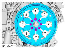
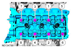
- 19.
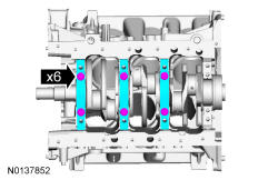
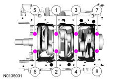
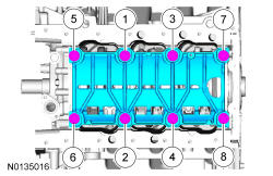
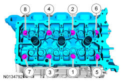
Tighten the main bearing bolts in the sequence shown in 2 stages.- Stage 1: Tighten fasteners 1 through 8 to 33 Nm (24 lb-ft).
- Stage 2: Tighten fasteners 1 through 8 an additional 135 degrees.
NOTE:
While tightening the main bearing vertical bolts, push the crankshaft forward and the No. 4 main bearing cap rearward to seat the crankshaft thrust washers.
- 20.
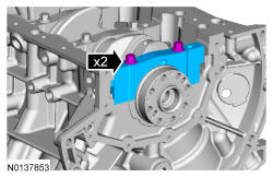
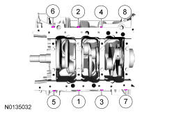
Install the new 8 main bearing cap side bolts. Tighten in the sequence shown in 2 stages.- Stage 1: Tighten fasteners 1 through 8 to 24 Nm (18 lb-ft).
- Stage 2: Tighten fasteners 1 through 8 an additional 180 degrees.
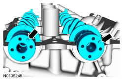
- 21.
Using 100-002 TOOL-4201-C, measure crankshaft end play.- Position the crankshaft to the rear of the cylinder block.
- Zero 100-002 TOOL-4201-C.
- Move the crankshaft to the front of the cylinder block. Note and record the crankshaft end play.
- 22.
Prepare the connecting rod and cap.- Insert the new bolts in the rod cap.
- Insert the upper and lower rod bearings into the rod and cap.
NOTE:
The rod cap installation must keep the same orientation as marked during disassembly or engine damage may occur.
- 23.
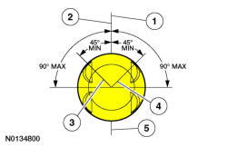
Before installing the pistons into the cylinder block, verify proper ring gap location.- Center line of the piston parallel to the wrist pin bore.
- Upper compression ring gap location.
- Upper oil control segment ring gap location.
- Lower oil control segment ring gap location.
- Expander ring and lower compression ring gap location.
- 24.
Using the Piston Ring Compressor, install the piston and connecting rod assemblies.
NOTE:
If the piston and connecting rod are to be reinstalled, they must be installed in the same orientation as disassembled.
NOTE:
If the piston and or connecting rod are being installed new, the piston rod orientation marks and the arrow on the top of the dome of the piston should be facing toward the front of the engine block.
NOTE:
Make sure the piston rings are positioned to specifications for installation. For additional information, refer to Piston .
NOTE:
Lubricate the pistons, piston rings, connecting rod bearings and the entire cylinder bores with clean engine oil.
NOTE:
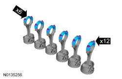
The next 3 steps are for all 6 connecting rods, rod caps and pistons. Only 1 connecting rod, rod cap and piston is shown.
NOTE:
Be sure not to scratch the cylinder wall or crankshaft journal with the connecting rod. Push the piston down until the connecting rod bearing seats on the crankshaft journal.
- 26.
Install the connecting rod cap and bolts. Tighten the bolts in 3 stages.- Stage 1: Tighten to 23 Nm (17 lb-ft).
- Stage 2: Tighten to 43 Nm (32 lb-ft).
- Stage 3: Tighten an additional degrees (90).
NOTE:
After installation of each piston, connecting rod, rod cap and bolts, rotate the crankshaft to verify smooth operation.
NOTE:
The rod cap installation must keep the same orientation as marked during disassembly or engine damage may occur.
- 27.
Repeat the previous 3 steps until all 6 piston, connecting rod and connecting rod cap assemblies are installed.
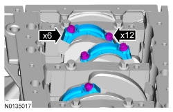
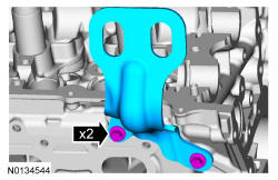
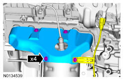
- 28.
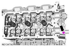
Install the main bearing cap support brace and the new bolts. Tighten in the sequence shown in 2 steps.- Stage 1: Tighten to 20 Nm (177 lb-in).
- Stage 2: Tighten an additional 180 degrees.
- 29.
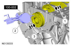
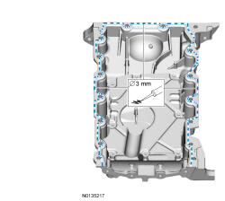
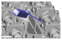
Apply a 3 mm (0.12 in) bead of Motorcraft ® High Performance Engine RTV Silicone to the sealing surface of the crankshaft rear seal retainer.
NOTE:
The stamped steel crankshaft rear seal retainer plate comes with the crankshaft rear seal.
NOTE:
The crankshaft rear seal retainer must be installed and the bolts tightened within 10 minutes of sealant application.
NOTE:
Failure to use Motorcraft ® High Performance Engine RTV Silicone may cause the engine oil to foam excessively and result in serious engine damage.

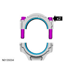
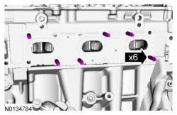
- 30.
Install the crankshaft rear seal retainer and the 8 bolts and tighten in sequence shown.- Tighten to 10 Nm (89 lb-in).
NOTE:
Lubricate the crankshaft rear seal with clean engine oil.
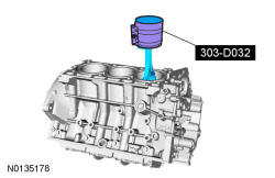
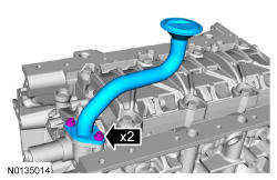
- 32.
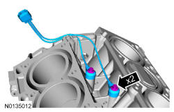
Using a new O-ring seal, install the oil pump screen and pickup tube and the 2 bolts.- Tighten to 10 Nm (89 lb-in).
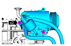
- 33.
Install the A/C compressor and the 2 bolts.- Stage 1: Tighten to 25 Nm (18 lb-ft).
NOTE:
The A/C compressor must be installed on the cylinder block and the 2 bolts tightened prior to installing the oil pan.
- 34.
Apply a 3 mm (0.12 in) bead of Motorcraft ® High Performance Engine RTV Silicone to the sealing surface of the oil pan.
NOTE:
Failure to use Motorcraft ® High Performance Engine RTV Silicone may cause the engine oil to foam excessively and result in serious engine damage.
- 35.
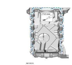
Apply a 5.5 mm (0.22 in) bead of Motorcraft ® High Performance Engine RTV Silicone to the 2 crankshaft seal retainer plate-to-cylinder block joint areas on the sealing surface of the oil pan.
NOTE:
The oil pan and the 4 specified bolts must be installed and the oil pan aligned to the cylinder block and A/C compressor within 4 minutes of sealant application. Final tightening of the oil pan bolts must be carried out within 60 minutes of sealant application.
NOTE:
Failure to use Motorcraft ® High Performance Engine RTV Silicone may cause the engine oil to foam excessively and result in serious engine damage.
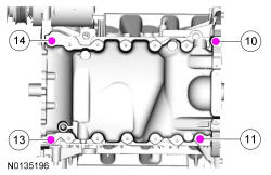
- 36.
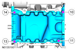
Install the oil pan and bolts 10, 11, 13 and 14.- Stage 1: Tighten to 3 Nm (27 lb-in).
- Stage 2: Loosen the bolts 180 degrees.
NOTE:
The oil pan and the 4 specified bolts must be installed within 4 minutes of the start of sealant application.
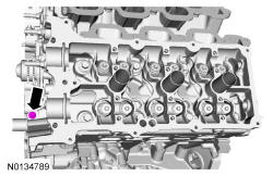
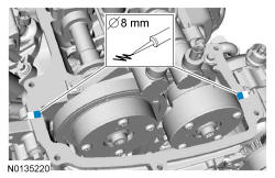
- 37.
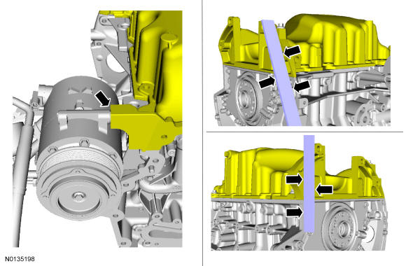
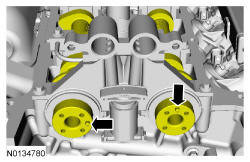
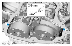
Align the oil pan to the cylinder block and the A/C compressor.- Position the oil pan so the mounting boss is against the A/C compressor and using a straightedge, align the oil pan flush with the rear of the cylinder block at the 2 areas shown.
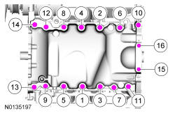
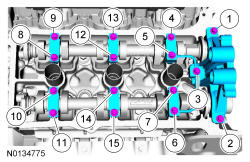
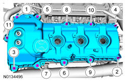
- 39.
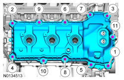
Install the remaining oil pan bolts. Tighten all the oil pan bolts in the sequence shown.- Stage 1: Tighten the large bolts (1-14) to 24 Nm (18 lb-ft).
- Stage 2: Tighten the small bolts (15 and 16) to 10 Nm (89 lb-in).
- 40.
Install the A/C compressor mounting stud and nut.- Tighten the stud to 9 Nm (80 lb-in) and the nut to 25 Nm (18 lb-ft).
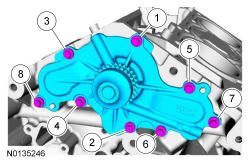
- 41.
Install the coolant pump and the 8 bolts. Tighten in the sequence shown in 2 stages:- Stage 1: Tighten to 10 Nm (89 lb-in).
- Stage 2: Tighten an additional 45 degrees.
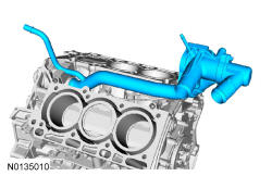
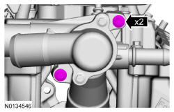
- 43.
Using a new O-ring seal, install the coolant inlet tube and thermostat assembly.
NOTE:
Apply clean engine coolant to the O-ring seal prior to installation.
- 44.
Install a new gasket, the RH cylinder head and 8 new bolts. Tighten in the sequence shown in 5 stages:- Stage 1: Tighten to 20 Nm (177 lb-in).
- Stage 2: Tighten to 35 Nm (26 lb-ft).
- Stage 3: Tighten 90 degrees.
- Stage 4: Tighten 90 degrees.
- Stage 5: Tighten 45 degrees.
- 46.
Install a new gasket, the LH cylinder head and 8 new bolts. Tighten in the sequence shown in 5 stages:- Stage 1: Tighten to 20 Nm (177 lb-in).
- Stage 2: Tighten to 35 Nm (26 lb-ft).
- Stage 3: Tighten 90 degrees.
- Stage 4: Tighten 90 degrees.
- Stage 5: Tighten 45 degrees.
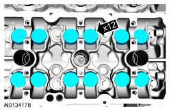
- 48.
Install the valve tappets.
NOTE:
LH shown, RH similar.
NOTE:
Coat the valve tappets with clean engine oil prior to installation.
NOTE:
The valve tappets must be installed in their original positions.
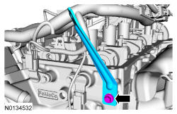
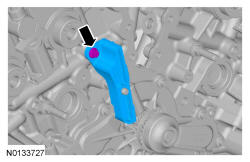
- 49.
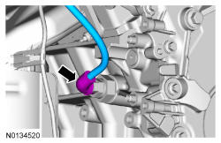
Install the upper intake manifold bracket and the bolt.- Tighten to 10 Nm (89 lb-in).
NOTE:
Align the bracket with the index mark made during removal.
- 52.
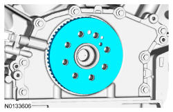
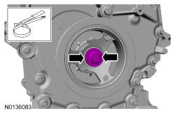
Position the crankshaft dowel pin in the 9 o'clock position.
NOTE:
The crankshaft must remain in the freewheeling position (crankshaft dowel pin at 9 o'clock) until after the camshafts are installed and the valve clearance is checked/adjusted. Do not turn the crankshaft until instructed to do so. Failure to follow this process will result in severe engine damage.
- 53.
Position the camshafts onto the RH cylinder head in the neutral position as shown.
NOTE:
Coat the camshafts with clean engine oil prior to installation.
- 54.
Position the 4 camshaft seals gaps as shown.
NOTE:
The camshaft seal gaps must be at the 12 o'clock position or damage to the engine may occur.
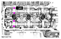
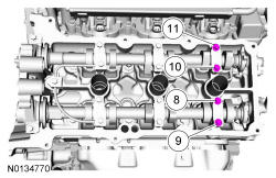
- 55.
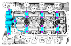
Install the 6 camshaft caps, mega cap, valve train oil tube and the 15 bolts in the sequence shown.- Tighten to 8 Nm (71 lb-in) then an additional 45 degrees.
NOTE:
Cylinder head camshaft bearing caps are numbered to verify that they are assembled in their original positions.
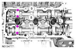
- 57.
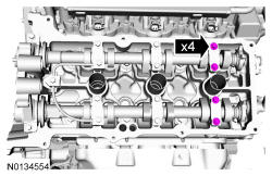
Tighten the 4 camshaft caps bolts in the sequence shown.- Tighten bolts 8, 9, 10 and 11 to 8 Nm (71 lb-in) then an additional 45 degrees.
- 58.
Using a feeler gauge, confirm that the valve tappet clearances are within specification. If valve tappet clearances are not within specification, the clearance must be adjusted by installing new valve tappet(s) of the correct size.
NOTE:
Use a camshaft sprocket bolt to turn the camshafts.
NOTE:
If any components are installed new, the engine valve clearance must be checked/adjusted or engine damage may occur.
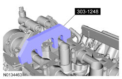
- 61.
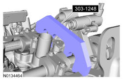
Install 303-1248 onto the flats of the RH camshafts.
NOTE:
The 303-1248 will hold the camshafts in the TDC position.
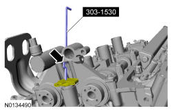
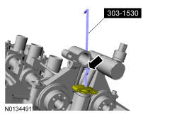
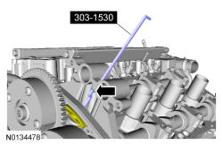
- 62.
Compress the RH secondary timing chain tensioner and install 303-1530 to retain the tensioner in the collapsed position.
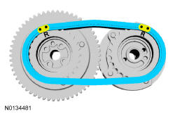
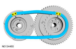
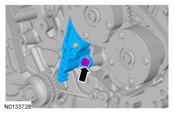
- 63.
Assemble the RH VCT assembly, the RH exhaust camshaft sprocket and the RH secondary timing chain.- Align the colored links with the timing marks.
- 64.
Position the 2 RH VCT assemblies and secondary timing chain onto the camshafts by aligning the holes in the VCT assemblies with the dowel pins in the camshafts.
NOTE:
It may be necessary to rotate the camshafts slightly, to install the RH secondary timing assembly.

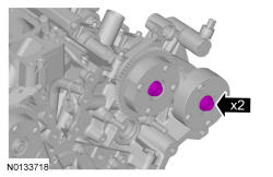
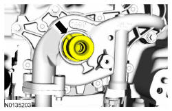
- 65.
Install the 2 new RH VCT bolts and tighten in 4 stages.- Stage 1: Tighten to 40 Nm (30 lb-ft).
- Stage 2: Loosen one full turn.
- Stage 3: Tighten 25 Nm (18 lb-ft).
- Stage 4: Tighten an additional 180 degrees.
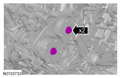
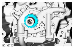
- 66.
Compress the RH secondary timing chain tensioner and remove the Secondary Chain Hold Down.- Make sure the secondary timing chain is centered on the timing chain tensioner guides.
NOTE:
The 2 VCT oil control solenoids are removed for clarity.
- 67.
Position the camshafts onto the LH cylinder head in the neutral position as shown.
NOTE:
Coat the camshafts with clean engine oil prior to installation.
- 68.
Position the 4 camshaft seals gaps as shown.
NOTE:
The camshaft seal gaps must be at the 12 o'clock position or damage to the engine may occur.
- 69.
Install the 6 camshaft caps, mega cap, valve train oil tube and the 15 bolts in the sequence shown.- Tighten to 8 Nm (71 lb-in) then an additional 45 degrees.
NOTE:
Cylinder head camshaft bearing caps are numbered to verify that they are assembled in their original positions.
- 71.
Tighten the 4 camshaft caps bolts in the sequence shown.- Tighten bolts 8, 9, 10 and 11 to 8 Nm (71 lb-in) then an additional 45 degrees.
- 72.
Using a feeler gauge, confirm that the valve tappet clearances are within specification. If valve tappet clearances are not within specification, the clearance must be adjusted by installing new valve tappet(s) of the correct size.
NOTE:
Use a camshaft sprocket bolt to turn the camshafts.
NOTE:
If any components are installed new, the engine valve clearance must be checked/adjusted or engine damage may occur.
- 75.
Install 303-1248 onto the flats of the LH camshafts.
NOTE:
The 303-1248 will hold the camshafts in the TDC position.
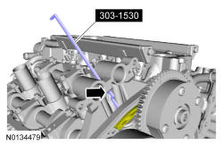
- 76.
Compress the LH secondary timing chain tensioner and install the 303-1530 to retain the tensioner in the collapsed position.
- 77.
Assemble the 2 LH VCT assemblies and the LH secondary timing chain.- Align the colored links with the timing marks.
- 78.
Position the 2 LH VCT assemblies and secondary timing chain onto the camshafts by aligning the holes in the VCT assemblies with the dowel pins in the camshafts.
NOTE:
It may be necessary to rotate the camshafts slightly, to install the LH secondary timing assembly.
- 79.
Install the 2 new LH VCT bolts and tighten in 4 stages.- Stage 1: Tighten to 40 Nm (30 lb-ft).
- Stage 2: Loosen one full turn.
- Stage 3: Tighten to 25 Nm (18 lb-ft).
- Stage 4: Tighten an additional 180 degrees.
- 80.
Compress the LH secondary timing chain tensioner and remove the 303-1530.- Make sure the secondary timing chain is centered on the timing chain tensioner guides.
NOTE:
The 2 VCT oil control solenoids are removed for clarity.
- 82.
Rotate the crankshaft clockwise 60 degrees to the TDC position (crankshaft dowel pin at 11 o'clock).
- 84.
Install the primary timing chain with the colored links aligned with the timing marks on the VCT assemblies and the crankshaft sprocket.
NOTE:
It may be necessary to rotate the camshafts slightly, to align the timing marks.
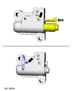
- 87.
Reset the primary timing chain tensioner.- Release the ratchet detent.
- Using a soft-jawed vise, compress the ratchet plunger.
- Align the hole in the ratchet plunger with the hole in the tensioner housing.
- Install a suitable lockpin.
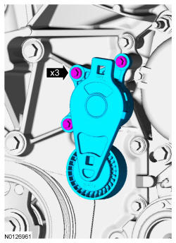
- 88.
Install the primary tensioner and the 2 bolts.- Tighten to 10 Nm (89 lb-in).
- Remove the lockpin.
NOTE:
It may be necessary to rotate the camshafts slightly to remove slack from the timing chain to install the tensioner.
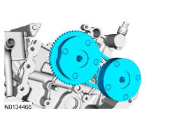
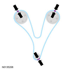
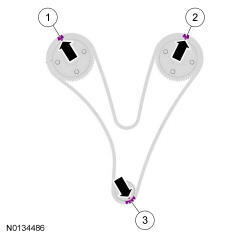
- 89.
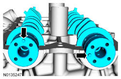
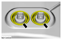
As a post-check, verify correct alignment of all timing marks.- There are 48 links in between the RH intake VCT assembly colored link (1) and the LH intake VCT assembly colored link (2).
- There are 35 links in between LH intake VCT assembly colored link (2) and the 2 crankshaft sprocket links (3).
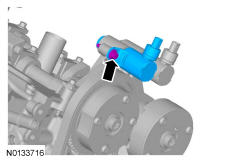
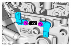
- 90.
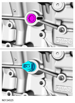
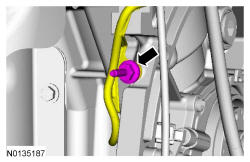
Install the LH intake VCT oil control solenoid and the bolt.- Tighten to 8 Nm (71 lb-in) then an additional 20 degrees.
NOTE:
Keep the VCT oil control solenoid clean of dirt and debris.
NOTE:
A slight twisting motion will aid in the installation of the VCT oil control solenoid.
NOTE:
Do not use excessive force when installing the VCT oil control solenoid. Damage to the mega cap could cause the cylinder head to be inoperable. If difficult to install the VCT oil control solenoid, inspect the bore and VCT oil control solenoid to ensure there are no burrs, sharp edges or contaminants present on the mating surface. Only clean the external surfaces as necessary.
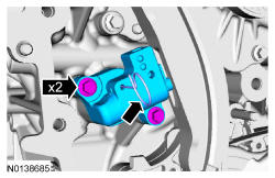
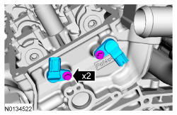
- 91.
Install the RH intake VCT oil control solenoid and the bolt.- Tighten to 8 Nm (71 lb-in) then an additional 20 degrees.
NOTE:
Keep the VCT oil control solenoid clean of dirt and debris.
NOTE:
A slight twisting motion will aid in the installation of the VCT oil control solenoid.
NOTE:
Do not use excessive force when installing the VCT oil control solenoid. Damage to the mega cap could cause the cylinder head to be inoperable. If difficult to install the VCT oil control solenoid, inspect the bore and VCT oil control solenoid to ensure there are no burrs, sharp edges or contaminants present on the mating surface. Only clean the external surfaces as necessary.
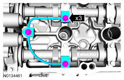
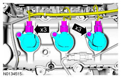
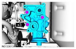
- 93.
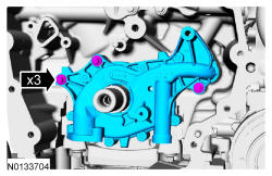
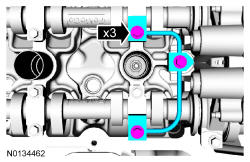
Install the RH valve train oil tube and the 3 bolts and tighten in 2 stages.- Stage 1: Tighten to 8 Nm (71 lb-in).
- Stage 2: Tighten an additional 45 degrees.
- 95.
Install the LH valve train oil tube and the 3 bolts and tighten in 2 stages.- Stage 1: Tighten to 8 Nm (71 lb-in).
- Stage 2: Tighten an additional 45 degrees.
- 96.
Clean the sealing surfaces of the cylinder heads, the cylinder block and the oil pan in the following sequence.- Remove any large deposits of silicone or gasket material.
- Apply Motorcraft ®Silicone Gasket Remover and allow to set for several minutes.
- Remove the Motorcraft ®Silicone Gasket Remover. A second application of Motorcraft ®Silicone Gasket Remover may be required if residual traces of silicone or gasket material remain.
- Apply Motorcraft ® Metal Surface Prep to remove any remaining traces of oil or coolant and to prepare the surfaces to bond. Do not attempt to make the metal shiny. Some staining of the metal surfaces is normal.
NOTE:
Do not use wire brushes, power abrasive discs or 3M Roloc ® Bristle Disk (2-in white part number 07528) to clean the sealing surfaces of engine block, cylinder heads, and oil pan. These tools can cause contamination that will cause premature engine failure. Remove all traces of the gasket.
NOTE:
Place clean, lint-free shop towels over exposed engine cavities. Carefully remove the towels so foreign material is not dropped into the engine. Any foreign material (including any material created while cleaning gasket surfaces) that enters the oil passages or the oil pan, may cause engine failure.
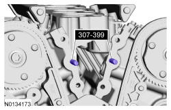
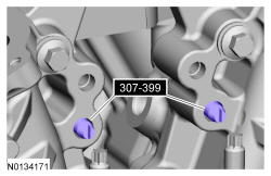
- 97.
Install 307-399.
NOTE:
Make sure the 2 locating dowel pins are seated correctly in the cylinder block.
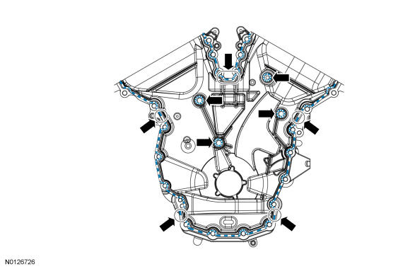
- 98.
Apply a 3 mm (0.1181 in) bead of Motorcraft ® High Performance Engine RTV Silicone to the sealing surface of the front cover.- Apply a 5.5 mm (0.22 in) bead of Motorcraft ® High Performance Engine RTV Silicone to the oil pan-to-cylinder block joint and the cylinder head-to-cylinder block joint areas of the engine front cover in 5 places as indicated.
NOTE:
The engine front cover and bolts 7, 8, 15, 17, 18, 21 and 22 must be installed within 4 minutes of the initial sealant application. The remainder of the engine front cover bolts must be installed and tightened within 35 minutes of the initial sealant application. If the time limits are exceeded, the sealant must be removed, the sealing area cleaned and sealant reapplied. To clean the sealing area, use Motorcraft ®Silicone Gasket Remover and Motorcraft ® Metal Surface Prep. Failure to follow this procedure can cause future oil leakage.
NOTE:
Failure to use Motorcraft ® High Performance Engine RTV Silicone may cause the engine oil to foam excessively and result in serious engine damage.
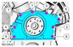
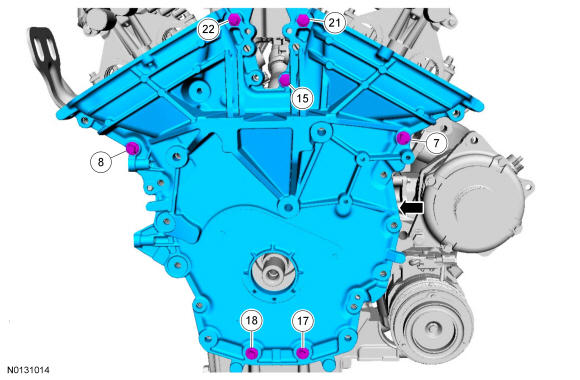
- 99.
Install the engine front cover and bolts 7, 8, 15, 17, 18, 21 and 22.- Tighten in sequence shown to 3 Nm (27 lb-in).
NOTE:
Make sure the 2 locating dowel pins are seated correctly in the cylinder block.
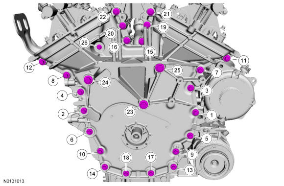
- 103.
Install the remaining engine front cover bolts. Tighten all of the engine front cover bolts in the sequence shown in 7 stages.- Stage 1: Tighten bolts 1 thru 22 to 10 Nm (89 lb-in).
- Stage 2: Tighten bolts 23 thru 25 to 15 Nm (133 lb-in).
- Stage 3: Tighten bolt 26 to 10 Nm (89 lb-in).
- Stage 4: Loosen bolt 26 one full turn.
- Stage 5: Tighten bolts 23 thru 25 to 30 Nm (22 lb-ft) plus an additional 90 degrees.
- Stage 6: Tighten bolts 1 thru 22 to 20 Nm (177 lb-in) plus an additional 45 degrees.
- Stage 7: Tighten bolt 26 to 10 Nm (89 lb-in) plus an additional 45 degrees.
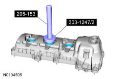
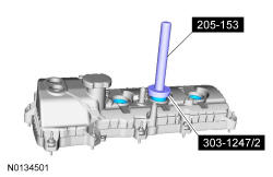
- 104.
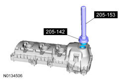
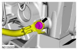
Using 303-1247/2 and 205-153 T80T-4000-W install the new spark plug tube seal(s).
NOTE:
Installation of new seals is only required if damaged seals were removed.
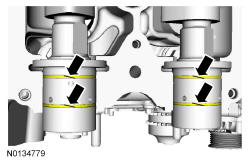
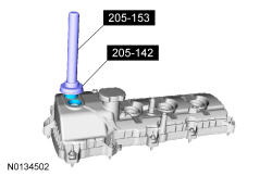
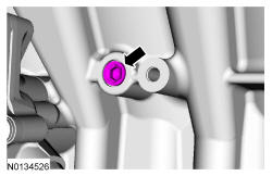
- 105.
Using 205-142 T80T-4000-J and 205-153 T80T-4000-W install the new VCT seal(s).
NOTE:
Installation of new seals is only required if damaged seals were removed.
- 106.
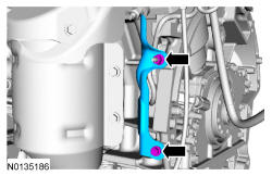
Apply an 8 mm (0.315 in) bead of Motorcraft ® High Performance Engine RTV Silicone to the engine front cover-to-Right Hand (RH) cylinder head joints.
NOTE:
If the valve cover is not installed and the fasteners tightened within 4 minutes, the sealant must be removed and the sealing area cleaned. To clean the sealing area, use Motorcraft ®Silicone Gasket Remover and Motorcraft ® Metal Surface Prep. Failure to follow this procedure can cause future oil leakage.
NOTE:
Failure to use Motorcraft ® High Performance Engine RTV Silicone may cause the engine oil to foam excessively and result in serious engine damage.
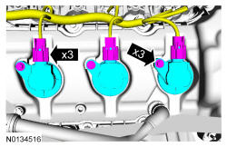
- 107.
Using a new gasket, install the RH valve cover and tighten the 3 bolts and 8 stud bolts.- Tighten in the sequence shown to 10 Nm (89 lb-in).
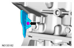
- 108.
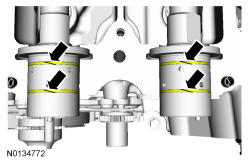
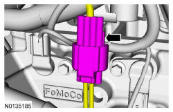
Make sure the VCT seals in the valve cover are below the top of the VCT oil control solenoid electrical connector or the VCT seal may leak oil.
- 110.
Install the 3 RH coil-on-plugs and the 3 bolts.- Tighten to 7 Nm (62 lb-in).
NOTE:
Apply a small amount of dielectric grease to the inside of the ignition coil-on-plug boots before attaching to the spark plugs.
- 111.
Using 303-1247/2 and 205-153 T80T-4000-W install the new spark plug tube seal(s).
NOTE:
Installation of new seals is only required if damaged seals were removed.
- 112.
Using 205-142 T80T-4000-J and 205-153 T80T-4000-W install the new VCT seal(s).
NOTE:
Installation of new seals is only required if damaged seals were removed.
- 113.
Apply an 8 mm (0.315 in) bead of Motorcraft ® High Performance Engine RTV Silicone to the engine front cover-to-Left Hand (LH) cylinder head joints.
NOTE:
If the valve cover is not installed and the fasteners tightened within 4 minutes, the sealant must be removed and the sealing area cleaned. To clean the sealing area, use Motorcraft ®Silicone Gasket Remover and Motorcraft ® Metal Surface Prep. Failure to follow this procedure can cause future oil leakage.
NOTE:
Failure to use Motorcraft ® High Performance Engine RTV Silicone may cause the engine oil to foam excessively and result in serious engine damage.
- 114.
Using a new gasket, install the LH valve cover and tighten the 4 bolts and 7 stud bolts.- Tighten in the sequence shown to 10 Nm (89 lb-in).
- 115.
Make sure the VCT seals in the valve cover are below the top of the VCT oil control solenoid electrical connector or the VCT seal may leak oil.
- 116.
Install the 3 LH coil-on-plugs and the 3 bolts.- Tighten to 7 Nm (62 lb-in).
NOTE:
Apply a small amount of dielectric grease to the inside of the ignition coil-on-plug boots before attaching to the spark plugs.
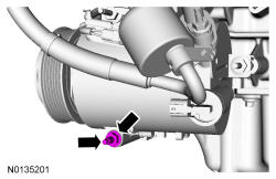
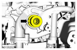
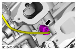
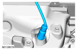
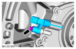
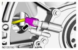
- 117.
Install the EOP switch.- Tighten to 14 Nm (124 lb-in) plus an additional 180 degrees.
NOTE:
Apply Thread Sealant with PTFE to the EOP switch threads.
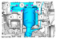
- 118.
Using a new gasket, install the oil filter adapter and the 3 bolts.- Tighten to 10 Nm (89 lb-in) plus an additional 45 degrees.
NOTE:
Oil filter adapter with oil cooler shown, oil filter adapter without oil cooler similar.
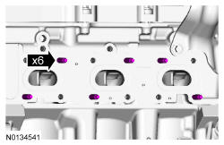
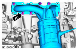
- 119.
If equipped, install a new oil cooler, new gaskets and the 6 bolts.- Tighten in the sequence shown to 10 Nm (89 lb-in).
NOTE:
A new oil cooler must be installed or severe damage to the engine may occur.
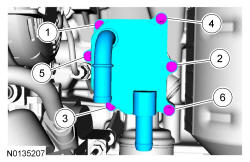
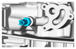
- 121.
Using a new O-ring seal, install the coolant inlet tube and thermostat assembly.
NOTE:
Apply clean engine coolant to the O-ring seal prior to installation.
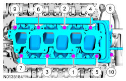
- 122.
Using new intake manifold and thermostat housing gaskets, install the lower intake manifold and the 10 bolts.- Tighten in the sequence shown to 10 Nm (89 lb-in).
NOTE:
If the engine is repaired or replaced because of upper engine failure, typically including valve or piston damage, check the intake manifold for metal debris. If metal debris is found, install a new intake manifold. Failure to follow these instructions can result in engine damage.
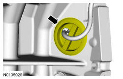
- 127.
Install the LH cylinder block drain plug.- Tighten to 16 Nm (142 lb-in) plus an additional 180 degrees.
- 128.
If equipped, install the block heater wiring harness onto the engine.- Stage 1: Tighten the cylinder block drain plug to 10 Nm (89 lb-in) plus an additional 180 degrees.
- Stage 2: Tighten the block heater to 40 Nm (30 lb-ft).
- 129.
If equipped with FWD, install 6 new RH catalytic converter manifold studs.- Tighten to 12 Nm (106 lb-in).
- 130.
If equipped with FWD, using a new gasket, install the RH catalytic converter manifold and 6 new nuts. Tighten in 2 stages in the sequence shown:- Stage 1: Tighten to 20 Nm (177 lb-in).
- Stage 2: Tighten to 25 Nm (18 lb-ft).
NOTE:
Failure to tighten the exhaust manifold nuts to specification a second time will cause the exhaust manifold to develop an exhaust leak.
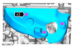
- 131.
If equipped with FWD, install the RH catalytic converter manifold heat shield, CMS wiring harness bracket and the 4 bolts.- Tighten to 10 Nm (89 lb-in).
- 133.
Using a new gasket, install the LH catalytic converter and 3 new lower LH catalytic converter manifold-to-cylinder head nuts. Tighten in 2 stages in the sequence shown:- Stage 1: Tighten the 3 lower LH catalytic converter manifold-to-cylinder head nuts to 25 Nm (18 lb-ft).
- Stage 2: Install the 3 new upper nuts and tighten the upper LH catalytic converter manifold-to-cylinder head nuts to 25 Nm (18 lb-ft).
- 135.
Install the LH HO2S.- Tighten to 48 Nm (35 lb-ft).
NOTE:
Apply High Temperature Nickel Anti-Seize Lubricant to the threads of the HO2S prior to installing.
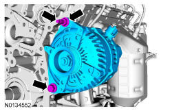
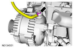
- 137.
Install the generator stud, generator and the nut and bolt.- Tighten the stud to 8 Nm (71 lb-in).
- Tighten the nut and bolt to 47 Nm (35 lb-ft).

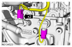
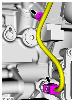
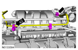
- 149.
Install the engine wiring harness to the RH valve cover.- Position the wiring harness and attach the 9 wiring harness retainers to the RH valve cover and stud bolts.
- Connect the CHT sensor wiring harness jumper electrical connector.
- Connect the 3 fuel injector electrical connectors.
- Connect and attach the RH CMS electrical connector.
- Connect the 2 VCT oil control solenoid electrical connectors.
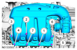
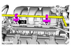
- 150.
Using a new gasket, install the intake manifold and the 7 bolts.- Tighten in the sequence shown in 2 stages.
- Stage 1: Tighten to 10 Nm (89 lb-in).
- Stage 2: Tighten an additional 45 degrees.
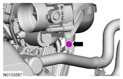
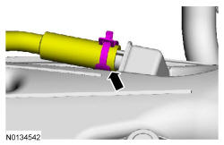
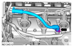
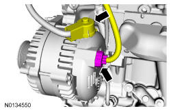
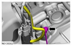
- 154.
Connect the EVAP vapor tube to the EVAP canister purge valve. REFER to Fuel System General Information .- Attach the EVAP vapor tube to the 2 retainers.
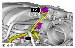
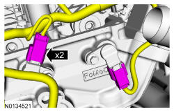
- 155.
Connect the EVAP canister purge valve and throttle body electrical connectors.- Attach the wiring harness pin-type retainer to the upper intake manifold.
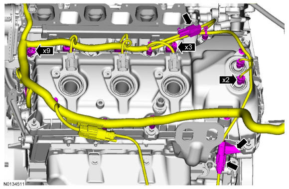
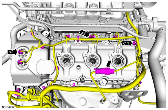
- 158.
Install the engine wiring harness to the LH valve cover.- Position the wiring harness and attach the 11 wiring harness retainers to the LH valve cover and stud bolts.
- Connect the 3 fuel injector electrical connectors.
- Connect and attach the LH HO2S electrical connector.
- Connect the 2 VCT oil control solenoid electrical connectors.
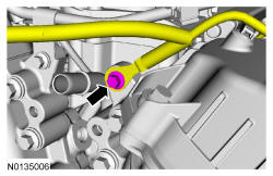
- 159.
Position the wire harness ground to the engine front cover and install the bolt.- Tighten to 10 Nm (89 lb-in).
- 161.
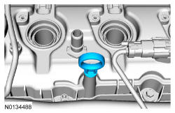
Install the crankcase vent tube. REFER to Fuel System General Information .
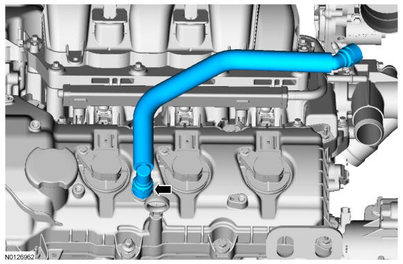
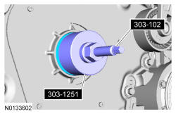
- 162.
Using the 303-102 T74P-6316-B and 303-1251, install a new crankshaft front seal.
NOTE:
Apply clean engine oil to the crankshaft front seal bore in the engine front cover.
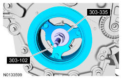
- 163.
Using the 303-102 T74P-6316-B and 303-335 T88T-6701-A, install the crankshaft pulley.
NOTE:
Lubricate the outside diameter sealing surfaces with clean engine oil.
NOTE:
Lubricate the crankshaft front seal inner lip with clean engine oil.
- 164.
Using the 303-D055 D85L-6000-A, install the crankshaft pulley washer and new bolt and tighten in 4 stages.- Stage 1: Tighten to 120 Nm (89 lb-ft).
- Stage 2: Loosen one full turn.
- Stage 3: Tighten to 50 Nm (37 lb-ft).
- Stage 4: Tighten an additional 90 degrees.
- 166.
If equipped, position the block heater wiring harness onto the engine and attach all of the harness retainers.- Connect the block heater electrical connector.