Driveline Angle Measurement
SPECIAL TOOL(S)
| Anglemaster II164-R2402 |

General Procedure
NOTE:
This procedure does not apply to CV joints, flex couplers or double cardan joints that are used in some driveshafts. This check is for single cross and roller style joints found in the driveshafts.
NOTE:
Prior to checking driveline angularity, inspect the U-joints for correct operation.
NOTE:
An incorrect driveline angle can cause a vibration or shudder. REFER to Noise, Vibration and Harshness
.
NOTE:
Driveline angularity is the angular relationship between the engine crankshaft, the driveshaft and the rear axle pinion. Factors determining driveline angularity include ride height, rear spring and engine mounts.
- 1.
Carry out the following preliminary setup steps:- Inspect the U-joints for correct operation.
- Park the vehicle on a level surface such as a drive on hoist, or back onto a front end alignment rack.
- Verify the curb position ride height is within specifications with the vehicle unloaded and all of the tires are inflated to their normal operating pressures.
- Calibrate the Anglemaster II Driveline Inclinometer/Protractor by placing it on a clean, flat level section of the frame rail and press the ALT-ZERO button.
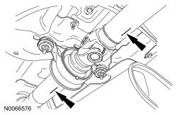
- 2.
Using the Anglemaster II Driveline Inclinometer/Protractor, measure the slope of the components in front and behind the center support bearing U-joint in the area indicated. Record the front component as angle A and the rear component as angle B.
- 3.NOTE: When 2 connected components slope in the same direction, subtract the smallest number from the larger number to find the U-joint operating angle. When 2 connected components slope in the opposite direction, add the measurements to find the U-joint operating angle.
Calculate the difference in the slope of the components to determine the U-joint operating angle.
- The U-joint operating angle is the angle formed by 2 yokes connected by a cross and bearing kit. Ideally, the operating angles on each connection of the driveshaft must: