Steering Wheel Auxiliary Controls: Notes
Component Location
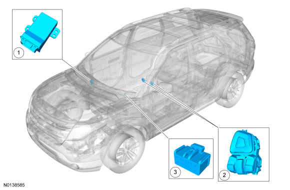
| Item | Description |
|---|---|
| 1 | Generic Function Module (GFM) |
| 2 | 14-way customer access inline connector |
| 3 | RH steering wheel switch |
Overview
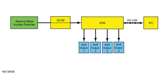
The steering wheel auxiliary controls allow the operation of 4 independent outputs of the Generic Function Module (GFM) by 2 switches mounted on the steering wheel.
System Operation
System Diagram
Network Message Chart
| Broadcast Message | Originating Module | Message Purpose |
|---|---|---|
| Police auxiliary switch display | Generic Function Module (GFM) | Indicates the status of the steering wheel auxiliary controls to the IPC. The IPC message center indicates the status of the Generic Function Module (GFM) grounded outputs. |
Steering Wheel Auxiliary Controls
The steering wheel auxiliary controls use 2 switches labeled AUX and 4 positions labeled 1, 2, 3 and 4. Each switch position controls an output of the Generic Function Module (GFM). Each output of the module is switched to ground when commanded on. When the switch is pressed to one of the positions, the IPC message center displays AUX1, AUX2, AUX3 or AUX4, depending on the position selected, the Generic Function Module (GFM) output will turn on and the outputs remain in that state until the switch is pressed again, then the outputs turn off.