PINPOINT TEST B : All Flashing LEDs Are Inoperative
- B1 CHECK THE LIGHTING CONTROL VOLTAGE SUPPLY CIRCUIT FOR AN OPEN
- Ignition OFF.
- Disconnect: Inline C4808A.
- Ignition ON.
- Measure:
Positive Lead Measurement / Action Negative Lead C4808A-1 Ground
Is the voltage greater than 11 volts?
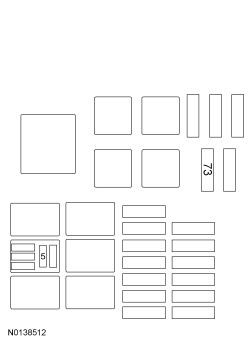
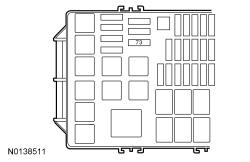
Yes GO to B2. No VERIFY BJB fuse 73 (20A) is OK. If OK, INSTALL the fuse and GO to B3. If not OK, REFER to the OEM ELECTRICAL WIRING DIAGRAM INTRODUCTION to identify the possible causes of the circuit short. - B2 CHECK THE LIGHTING CONTROL GROUND CIRCUIT
Is the voltage greater than 11 volts?
Yes VERIFY the lighting and siren control module (if equipped) 20A main power fuse in the lighting relay center or lighting and siren control module 10A output fuses are OK. If OK, GO to B7. If not OK, REFER to the OEM ELECTRICAL WIRING DIAGRAM INTRODUCTION to identify the possible causes of the circuit short. No REPAIR the circuit. - B3 CHECK THE LIGHTING CONTROL VOLTAGE SUPPLY CIRCUIT FOR AN OPEN
- Ignition OFF.
- Measure:
Positive Lead Measurement / Action Negative Lead C4808A-1 Fuse 73 (20A)
Is the resistance less than 3 ohms?
Yes GO to B4. No REPAIR the circuit. - B4 CHECK THE POLICE RUN/START RELAY OUTPUT CIRCUIT FOR AN OPEN
- Disconnect: Police Run/Start Relay.
- Measure:
Positive Lead Measurement / Action Negative Lead Police Run/Start Relay Pin 5 Fuse 73 (20A)
Is the resistance less than 3 ohms?
Yes GO to B5. No REPAIR the circuit. - B5 CHECK THE RUN/START RELAY VOLTAGE SUPPLY
- Ignition ON.
- Measure:
Positive Lead Measurement / Action Negative Lead Police Run/Start Relay Pin 2 Ground Police Run/Start Relay Pin 3 Ground
Are the voltages greater than 11 volts?
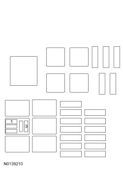
Yes GO to B6. No VERIFY BJB fuse 24 (40A) or 93 (5A) is OK. If OK, REPAIR the circuit. If not OK, REFER to the OEM ELECTRICAL WIRING DIAGRAM INTRODUCTION to identify the possible causes of the circuit short. - B6 CHECK THE RUN/START RELAY GROUND CIRCUIT
- Measure:
Positive Lead Measurement / Action Negative Lead Police Run/Start Relay Pin 3 Police Run/Start Relay Pin 1
Is the voltage greater than 11 volts?
Yes INSTALL a new police run/start relay. No REPAIR the circuit. - Measure:
- B7 CHECK THE CONTROL HEAD
- Replace the suspect control head with a known good control head.
- Operate the system and determine if the concern is still present.
Is the concern still present?
Yes INSTALL a new communication cable between the control head and the lighting relay center or lighting and siren control module. TEST the system for normal operation. If the concern returns, GO to B8. No INSTALL a new control head. - B8 CHECK FOR CORRECT LIGHTING CONTROL OPERATION
- For vehicles with lighting and siren control, disconnect and inspect all the lighting and siren control module connectors and jumpers.
- For vehicles with lighting control only, disconnect and inspect all the lighting relay center connectors and jumpers.
- Repair:
- corrosion (install new connector or terminals - clean module pins)
- damaged or bent pins - install new terminals/pins as necessary
- pushed-out-pins - install new pins as necessary
- For vehicles with lighting and siren control, reconnect the lighting and siren control module connectors and all previously disconnected exterior system connectors. Make sure they seat and latch correctly.
- For vehicles with lighting control only, reconnect the lighting relay center connectors and all previously disconnected exterior system connectors. Make sure they seat and latch correctly.
- Operate the system and determine if the concern is still present.
Is the concern still present?
Yes CHECK OASIS for any applicable TSBs. If a TSB exists for this concern, DISCONTINUE this test and FOLLOW TSB instructions. If no TSBs address this concern, CONTACT Whelen Service/Diagnostics at 1-860-526-9504, extension 8308. No The system is operating correctly at this time. The concern may have been caused by module connections. ADDRESS the root cause of any connector or pin issues.