Balance Shaft Backlash
WARNING: This page is about a different variant/trim than selected.
Special Tool(s)
| Dial Indicator Gauge With Holding Fixture 100-002TOOL-4201-C | |
| Timing Peg, Crankshaft TDC 303-507 |


General Procedure
- 1.
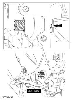
Install the 303-507 and rotate the crankshaft slowly clockwise until the crankshaft balance weight is up against the 303-507. The engine is now at TDC.
- 3.
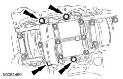
Remove the 4 bolts and the balancer unit.
NOTE:
Due to the precision interior construction of the balancer unit, it should not be disassembled.
- 5.
Install the master adjustment shims (No. 50) on the seat faces of the balancer unit.
NOTE:
Visually inspect the balancer unit gear for damage and verify that the shaft turns smoothly. If there is any damage or malfunction, replace the balancer unit.
- 6.
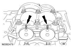
With the balancer unit shaft marks at the TDC position, slowly install the balancer unit to the cylinder block to avoid interference between the crankshaft drive gear and the balancer unit driven gear.
- 7.
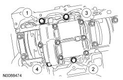
Install the balancer unit bolts.- Tighten in the sequence shown in 2 stages.
- Stage 1: Tighten to 25 Nm (18 lb-ft).
- Stage 2: Tighten to 42 Nm (31 lb-ft).
- Tighten in the sequence shown in 2 stages.
- 8.
Remove the 303-507.- Rotate the crankshaft to confirm that there are no meshing problems between the balancer unit gear and the crankshaft gear.
- 9.
Install the 303-507 and rotate the crankshaft slowly clockwise until the crankshaft balance weight is up against the 303-507.- Remove the 303-507.
- 10.
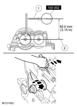
Position the 100-002 TOOL-4201-C as shown. Measure the gear backlash.- Position the 100-002 TOOL-4201-C (1) on the Allen wrench 80 mm (3.149 in) above the driven gear shaft center (2) on the balancer unit.
- Rotate the crankshaft clockwise and measure the backlash at all of the following 6 positions: 10 degrees, 30 degrees, 100 degrees, 190 degrees, 210 degrees and 280 degrees.
NOTE:
For an accurate measurement while measuring the gear backlash, insert a screwdriver as shown into the crankshaft No. 1 crankweight area and set both the rotation and the thrust direction with the screwdriver, using a prying action as shown.
NOTE:
The measurement must be taken with the 100-002 TOOL-4201-C, a 5-mm Allen wrench and worm clamp set up as shown. Mark the Allen wrench with a file 80 mm (3.149 in) above the driven gear shaft center. Make sure the worm clamp and Allen wrench are not touching the balance shaft housing.
NOTE:
Measure the backlash and verify that it is within specified range at all of the following 6 positions: 10 degrees, 30 degrees, 100 degrees, 190 degrees, 210 degrees and 280 degrees. It will be necessary to reset the measuring equipment between measurements.
- 11.
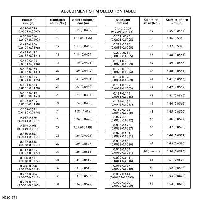
Using the backlash measurement, select the proper shims from the Adjustment Shim Selection Table.- Remove the balancer unit from the cylinder block.
- Install the selected adjustment shims on the seat faces of the balancer unit.
NOTE:
If maximum backlash exceeds 0.120 mm (0.0047 in), install a new balancer unit.
- 12.
Install the 303-507 and rotate the crankshaft slowly clockwise until the crankshaft balance weight is up against the 303-507. The engine is now at TDC.
- 13.
With the balancer unit shaft marks in the TDC position, slowly install the balancer unit to the cylinder block to avoid interference between the crankshaft drive gear and the balancer unit driven gear.
- 14.
Install the balancer unit bolts.- Tighten in the sequence shown in 2 stages.
- Stage 1: Tighten to 25 Nm (18 lb-ft).
- Stage 2: Tighten to 42 Nm (31 lb-ft).
- Tighten in the sequence shown in 2 stages.
- 15.
Position the 100-002 TOOL-4201-C as shown. Measure the gear backlash.- Position the 100-002 TOOL-4201-C (1) on the Allen wrench 80 mm (3.149 in) above the driven gear shaft center (2) on the balancer unit.
- Rotate the crankshaft clockwise and measure the backlash at all of the following 6 positions: 10 degrees, 30 degrees, 100 degrees, 190 degrees, 210 degrees and 280 degrees.
- If the backlash exceeds the specified range of 0.020 to 0.120 mm (0.0008 to 0.0047 in), install a new balancer unit and repeat the procedure.
NOTE:
For an accurate measurement while measuring the gear backlash, insert a screwdriver as shown into the crankshaft No. 1 crankweight area and set both the rotation and the thrust direction with the screwdriver, using a prying action as shown.
NOTE:
The measurement must be taken with the 100-002 TOOL-4201-C, a 5-mm Allen wrench and worm clamp set up as shown. Mark the Allen wrench with a file 80 mm (3.149 in) above the driven gear shaft center. Make sure the worm clamp and Allen wrench are not touching the balance shaft housing.
NOTE:
Remeasure the backlash and verify that it is within specified range at all of the following 6 positions: 10 degrees, 30 degrees, 100 degrees, 190 degrees, 210 degrees and 280 degrees. It will be necessary to reset the measuring equipment between measurements.