Intake Manifold: Installation
WARNING: This page is about a different variant/trim than selected.
NOTE:
If the engine is repaired or replaced because of upper engine failure, typically including valve or piston damage, check the intake manifold for metal debris. If metal debris is found, install a new intake manifold. Failure to follow these instructions can result in engine damage.
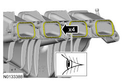
- 1.
Visually inspect the intake manifold gaskets for nicks, cuts and abrasions. If these conditions are not present, the gaskets may be re-used.
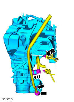
- 2.
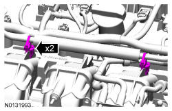
Position the intake manifold and connect the crankcase ventilation oil separator tube.- Attach the 2 KS wiring harness retainers from the intake manifold.
- Connect the TB electrical connector and attach the wiring harness retainer to the TB.
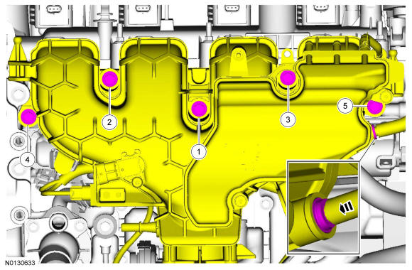
- 3.
Install the intake manifold and the 5 bolts.- Tighten in the sequence shown to 20 Nm (177 lb-in).
- Install the vacuum tube into the quick connect coupling.
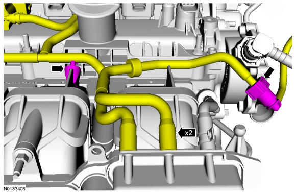
- 4.
Connect the 2 vacuum hoses to the intake manifold.- Connect the vacuum tube quick connect coupling. REFER to Fuel System General Information .
- Attach the vacuum hose retainer to the intake manifold.
- 6.
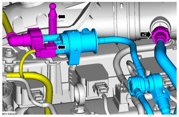
Install the EVAP canister purge valve and EVAP tube assembly.- Install the engine appearance cover mounting stud.
- Tighten to 5 Nm (44 lb-in).
- Connect the EVAP canister purge valve electrical connector.
- Connect the EVAP tube to the EVAP canister purge valve and the ACL outlet pipe. REFER to Fuel System General Information .
- Install the engine appearance cover mounting stud.
- 7.
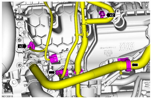
Connect the FRP sensor and MAP sensor electrical connectors.- Attach the 2 EVAP tube retainers to the intake manifold.
- Attach the heater hose to the retaining clip.
- 8.
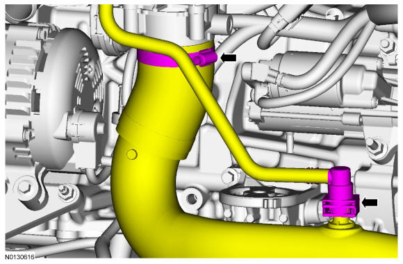
Connect the CAC outlet tube to the TB.- Tighten the clamp to 5 Nm (44 lb-in).
- Connect the EVAP tube to the CAC outlet tube. REFER to Fuel System General Information .
- 10.
Connect the battery ground cable. REFER to Battery, Mounting and Cables .