Fuel Rail: Installation
WARNING: This page is about a different variant/trim than selected.
- 1.NOTE: A clean working environment is essential to prevent dirt or foreign material contamination.
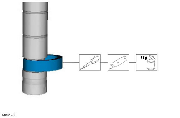
- 2.NOTE: Do not attempt to cut the lower Teflon® seal without first pulling it away from the fuel injector or damage to the injector may occur.NOTE: Use care when removing the lower Teflon® seals, not to scratch, nick or gouge the fuel injectors.
- 1.
Pull the lower Teflon® seal away from the injector.
- 2.
Carefully cut and discard the lower fuel injector Teflon® seals.
- 1.
- 3.
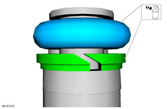
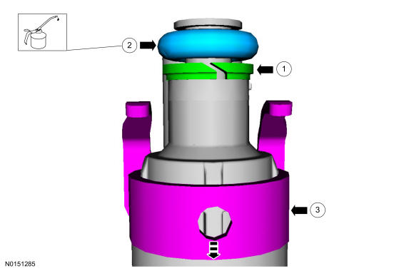
- 1.NOTE: Do not lubricate the new lower Teflon® fuel injector seals.
Special Tool(s): 310-207.
- 2.NOTE: Once the Teflon® seal is installed on the Teflon® Seal Guide 310-207 (part of the Fuel Injector Seal Installer), it should immediately be installed onto the fuel injector to avoid excessive expansion of the Teflon® seal.NOTE: Make sure that new lower fuel injector Teflon® seals are installed.
Special Tool(s): 310-207.
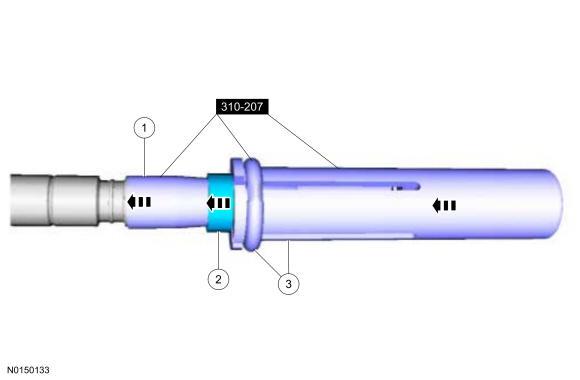
- 3.
Using the Pusher Tool 310-207 (part of the Fuel Injector Seal Installer), slide the Teflon® seals off of the Teflon® Seal Guide and into the groove on the fuel injectors. Special Tool(s): 310-207.
- 1.
- 4.NOTE: Install the fuel injectors into the cylinder head within 15 minutes of sizing the seals due to Teflon® seal expansion.
- 1.NOTE: Make sure the Teflon® seal is fully seated in the groove on the fuel injector before sizing the Teflon® seal.
Some Teflon® seal massaging with your fingers before the Teflon® seal sizer tool is installed will aid in installing the Teflon® seal sizer tool.
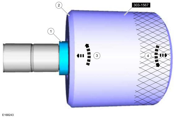
- 2.
Position the Teflon® seal sizer tool 303-1567 with the larger opening towards the Teflon® seal. Push while turning the Teflon® seal sizer tool 180 degrees. Special Tool(s): 303-1567.
- 3.
Once the Teflon® seal sizer tool 303-1567 is installed, check and make sure the Teflon® seal is in the sizing portion of the Teflon® seal sizer tool. After one minute, turn the Teflon® seal sizer tool back 180 degrees and remove.
- 1.
- 5.NOTE: Use new fuel injector O-ring seals that are made of special fuel-resistant material. The use of ordinary O-ring seals may cause the fuel system to leak. Do not reuse the O-ring seals.NOTE: Do not lubricate the new lower Teflon® fuel injector seals.NOTE: Make sure that new upper fuel injector O-ring seals 9229, new upper fuel injector O-ring seal support rings 9229 and new fuel injector retainer clips 9P847 are installed.
Material: Motorcraft® SAE 5W-30 Premium Synthetic Blend Motor Oil.
- 6.NOTE: The anti-rotation finger of the fuel injector clip must slip into the groove of the fuel rail cup.NOTE: The fuel rail pressure sensor must be replaced if it is removed from the fuel rail. REFER to Electronic Engine Controls
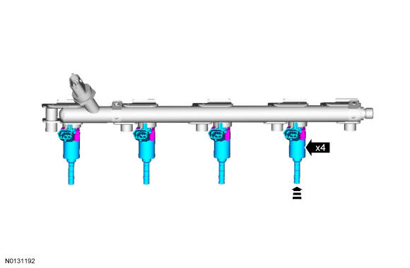
- 7.NOTE: Do not lubricate the new lower Teflon® fuel injector seals.NOTE: Push down on the fuel rail face above the injectors.
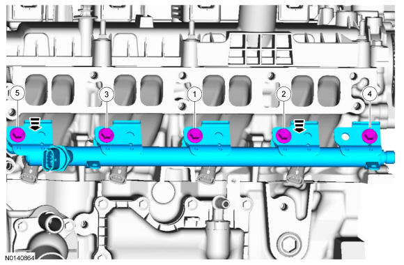
Tighten the 5 fuel rail bolts in the following 2 stages.
- Stage 1: 8 Nm (71 lb-in) in the sequence shown in illustration.
- Stage 2: 26 degrees in the sequence shown in illustration.
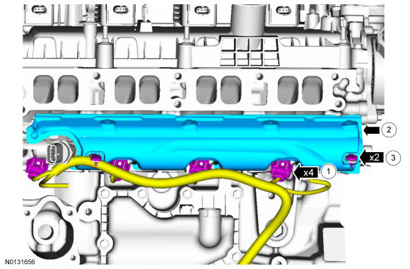
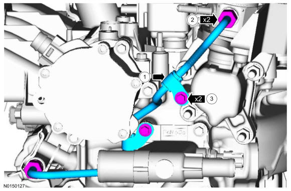
- 9.NOTE: Only tighten the 2 high pressure fuel tube flare nuts finger tight at this stage.NOTE: Only tighten the 2 high pressure fuel tube bracket bolts finger tight at this stage.NOTE: Make sure that a new high pressure fuel tube 9J323 is installed.
- 1.
- 2.
Calculate the correct torque wrench setting for the following torque. REFER to Service Information .- Stage 1: Using a torque adapter, 15 Nm (133 lb-in).
- Stage 2: 30 degrees.
- 3.
10 Nm.
- 1.
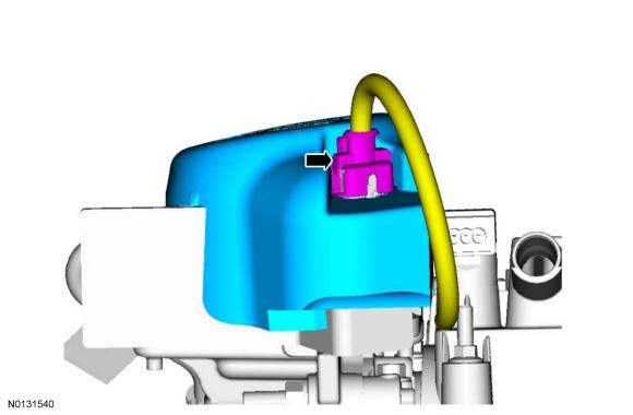
- 10.NOTE: When removing or installing the fuel injection pump noise insulator, spreading the openings will reduce the risk of damage.
- 11.
Install the intake manifold. Refer to ENGINE - 2.0L GTDI .
- 12.
Connect the battery ground cable. REFER to Battery, Mounting and Cables .
- 13.
Pressurize the fuel system. REFER to Fuel System - General Information .