Instrument Cluster and Panel Illumination: Notes
Overview
Dimmable Backlighting
Dimmable illumination provides backlighting to switches and control components when the parking lamps are on. The level of intensity is adjusted by pressing the instrument panel dimmer switch up to increase intensity or down to decrease intensity.
Non-dimmable Backlighting
Non-dimmable illumination provides backlighting to the door lock and window control switches when the accessory relay is energized.
System Operation
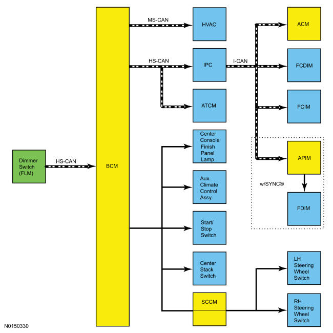
System Diagram
Network Message Chart BCM Network Input Messages
| Broadcast Message | Originating Module | Message Purpose |
|---|---|---|
| Dimmer switch status | FLM | The FLM sends a digital dimmer switch status to the BCM. The BCM then outputs networked illumination level messages and non-networked voltage outputs to control the illumination level. |
ATCM, HVAC Module and IPC Network Input Messages
| Broadcast Message | Originating Module | Message Purpose |
|---|---|---|
| Illumination dimming level | BCM | Used to command illumination level. |
ACM, APIM, FCIM and FCDIM Network Input Messages
| Broadcast Message | Originating Module | Message Purpose |
|---|---|---|
| Illumination dimming level | IPC | Used to command illumination level. |
Dimmable Backlighting
The dimmable switches and components are illuminated when the parking lamps are on. The instrument panel dimmer switch, which is integral to the FLM, controls all dimmable interior illuminated components. On vehicles equipped with autolamps, if the exterior lamps are activated during the daytime, the message center illumination remains at full intensity and does not dim from the instrument panel dimmer switch during this condition. If the vehicle travels under a bridge or in a tunnel, the low level of ambient light causes the illumination level of the message center to change to the level set by the instrument panel dimmer switch. The message center illumination changes back to full intensity when the intense ambient light is restored.
When the parking lamps are on, the BCM sends a pulse-width modulated voltage to the non-networked dimmable components and switches based on input received from the instrument panel dimmer switch (part of the FLM).
The BCM also sends the illumination dimming level message over the network. If a receiving module receives invalid backlighting data from the BCM for 5 seconds or less, the receiving module defaults the backlighting to the last setting.
If the receiving module does not receive the backlighting status message from the BCM or if the data received is deemed invalid for more than 5 seconds, the receiving module sets a DTC in continuous memory and defaults the backlighting to full nighttime intensity.
Non-Dimmable Backlighting
When the accessory delay relay is energized, switched voltage is supplied to the window control and door lock control switches. REFER to Glass, Frames and Mechanisms , Delayed Accessory Power.
Field-Effect Transistor (FET) Protection
REFER to Multifunction Electronic Modules , Field Effect Transistor (FET) Protection.
Dark Car Feature - Police Package
With the engine running and the headlamps and parking lamps off, the dark car feature allows the use of 2 dimmer settings, one slightly visible and the other completely dark.