Climate Control - DATC: Notes
Component Location
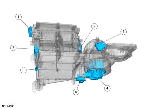
| Item | Description |
|---|---|
| 1 | Defrost/panel/floor mode door actuator |
| 2 | RH temperature blend door actuator |
| 3 | Air inlet mode door actuator |
| 4 | Blower motor |
| 5 | Blower motor speed control |
| 6 | A/C evaporator discharge air temperature sensor |
| 7 | LH temperature blend door actuator |
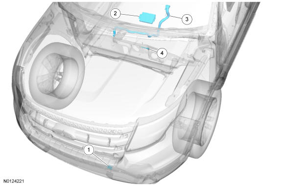
| Item | Description |
|---|---|
| 1 | AAT sensor |
| 2 | HVAC module |
| 3 | In-vehicle temperature and humidity sensor |
| 4 | A/C evaporator discharge air temperature sensor |
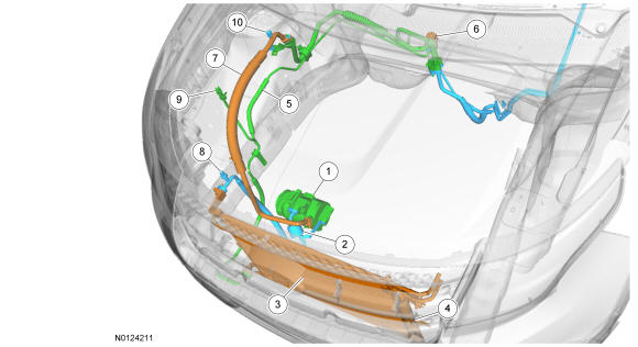
| Item | Description |
|---|---|
| 1 | A/C compressor |
| 2 | Compressor-to-condenser discharge line |
| 3 | Condenser core |
| 4 | Integrated receiver-drier |
| 5 | TXV manifold and tube assembly |
| 6 | TXV |
| 7 | Evaporator-to-compressor suction line |
| 8 | A/C pressure transducer |
| 9 | High-pressure service gauge port valve |
| 10 | Low-pressure service gauge port valve |
Overview
- The A/C refrigerant of all vehicles must be identified and analyzed prior to refrigerant charging. Failure to do so can contaminate the shop bulk refrigerant and other vehicles.
- Do not add R-12 refrigerant to an A/C system that requires the use of R-134a refrigerant. These 2 types of refrigerant must never be mixed. Doing so can damage the A/C system.
- Charge the A/C system with R-134a refrigerant gas while the engine is running only at the low-pressure side to prevent refrigerant slugging from damaging the A/C compressor.
- Use only R-134a refrigerant. Due to environmental concerns, when the A/C system is drained, the refrigerant must be collected using refrigerant recovery/recycling equipment. Federal, State/Provincial and/or local laws REQUIRE that R-134a be recovered into appropriate recovery equipment and the process be conducted by qualified technicians who have been certified by an approved organization, such as ASE or MACS. Use of a recovery machine dedicated to R-134a is necessary to reduce the possibility of oil and refrigerant incompatibility concerns. Refer to the instructions provided by the equipment manufacturer when removing refrigerant from or charging the A/C system.
- Refrigerant R-134a must not be mixed with air for leak testing or used with air for any other purpose above atmospheric pressure. R-134a is combustible when mixed with high concentrations of air and higher pressures.
- A number of manufacturers are producing refrigerant products that are described as direct substitutes for refrigerant R-134a. The use of any unauthorized substitute refrigerant can severely damage the A/C components. If repair is required, use only new or recycled refrigerant R-134a.
- Never open or loosen a connection before recovering the refrigerant.
- When loosening a connection, if any residual pressure is evident, allow it to leak out before opening the fitting.
- Evacuate a system that has been opened to install a new component or one that has discharged through leakage before charging.
- Seal open fittings with a cap or plug immediately after disconnecting a component from the system.
- Clean the outside of the fittings thoroughly before disconnecting a component from the system.
- Do not remove the sealing caps from a new component until ready to install.
- Refrigerant oil will absorb moisture from the atmosphere if left uncapped. Do not open an oil container until ready to use and install the cap immediately after using. Store the oil in a clean, moisture-free container.
- Install a new O-ring seal before connecting an open fitting. Coat the fitting and O-ring seal with Polyalkylene Glycol (PAG) oil before connecting.
- When installing a refrigerant line, avoid sharp bends. Position the line away from the exhaust or any sharp edges that can chafe the line.
- Tighten threaded fittings only to specifications. The steel and aluminum fittings used in the refrigerant system will not tolerate overtightening.
- When disconnecting a fitting, use a wrench on both halves of the fitting to prevent twisting of the refrigerant lines or tubes.
- Do not open a refrigerant system or uncap a new component unless it is as close as possible to room temperature. This will prevent condensation from forming inside a component that is cooler than the surrounding air.
The HVAC system maintains the selected vehicle interior temperature by heating and/or cooling the air depending on the HVAC control panel selection.
- During A/C operation, the system reduces the relative humidity of the air inside the vehicle.
- The driver may override the automatic mode of operation.
- The temperature control setting is the desired cabin air temperature.
- The blower motor control override buttons vary the blower motor speed.
- The driver side and passenger side temperature settings can be individually controlled.
System Operation
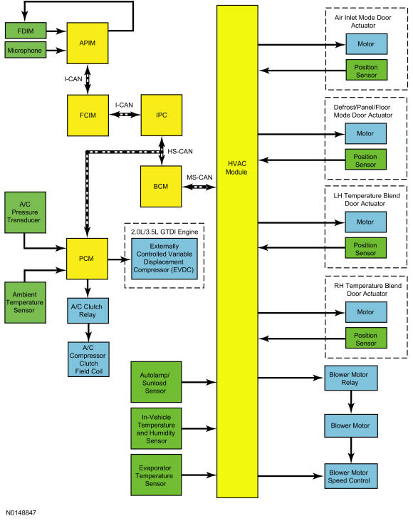
System Diagram
Network Message Chart
Module Network Input Messages - FCIM
| Broadcast Message | Originating Module | Message Purpose |
|---|---|---|
| Climate Control touchscreen and voice requests | APIM | This message contains both the climate control system voice commands as well as all climate control system touch screen inputs. |
| Climate control status | HVAC | This message contains the HVAC mode status for the mode indicators. |
Module Network Input Messages - IPC
| Broadcast Message | Originating Module | Message Purpose |
|---|---|---|
| Climate control requests (gateway) | FCIM | This message contains the HVAC temperature setting for the IPC display. |
| Climate control seat requests | FCIM | This message contains the HVAC blower motor setting for the IPC display. |
| Climate control information status | FCIM | This message contains the HVAC temperature and blower motor setting from the touch screen controls for the IPC display. |
Module Network Input Messages - APIM
| Broadcast Message | Originating Module | Message Purpose |
|---|---|---|
| Driver temperature setting | FCIM | This message contains the HVAC temperature setting for the touch screen display. |
| Front blower request | FCIM | This message contains the HVAC blower motor setting for the touch screen display. |
| Driver temperature units | HVAC | This message contains the HVAC driver temperature setting. |
| Passenger temperature units | HVAC | This message contains the HVAC passenger temperature setting. |
| Front fan bar display | HVAC | This message contains the HVAC blower motor setting. |
Module Network Input Messages - PCM
| Broadcast Message | Originating Module | Message Purpose |
|---|---|---|
| A/C request (gateway) | HVAC module | This message requests the A/C compressor clutch to be engaged. |
Module Network Input Messages - HVAC module
| Broadcast Message | Originating Module | Message Purpose |
|---|---|---|
| Climate control requests (gateway) | FCIM | This message contains all climate control system controls requests except blower motor speed. |
| Climate control seat requests (gateway) | FCIM | This message contains the climate control system controls request for blower motor speed. |
| Climate control information status | FCIM | This message contains the climate control system controls request from the MyTemp button. |
| Remote start status | BCM | This message contains the climate control system controls request for remote start. |
| A/C clutch status | PCM | This message contains the A/C compressor clutch status. |
| Ambient air temperature | PCM | This message contains raw value from the ambient temperature sensor. |
The Refrigerant Cycle
During stabilized conditions (Air Conditioning (A/C) system shutdown), the refrigerant pressures are equal throughout the system. When the A/C compressor is in operation, it uses a piston pump to compress the cool vapor, causing it to become high-temperature/high-pressure vapor. The high-temperature/high-pressure vapor is then released into the top of the A/C condenser core.
The A/C condenser, being close to ambient temperature, causes the refrigerant vapor to condense into a liquid when heat is removed from the refrigerant by ambient air passing over the fins and tubing. The now liquid refrigerant, still at high pressure, exits from the bottom of the A/C condenser and enters the inlet side of the A/C receiver-drier (integral to the condenser). The receiver-drier is designed to remove moisture from the refrigerant system.
The outlet of the receiver-drier is connected to the TXV. The TXV provides the orifice, which is the restriction in the refrigerant system, and separates the high and low pressure sides of the A/C system. As the liquid refrigerant passes across this restriction, its pressure and boiling point are reduced. An internal temperature sensing bulb senses the temperature of the refrigerant flowing out of the evaporator core and adjusts an internal pin-type valve to meter the refrigerant flow into the evaporator core. The internal pin-type valve decreases the amount of refrigerant entering the evaporator core at lower temperatures and increases the amount of refrigerant entering the evaporator core at higher temperatures.
The liquid refrigerant is now at its lowest pressure and temperature. As it passes through the A/C evaporator, it absorbs heat from the airflow passing over the plate/fin sections of the A/C evaporator. This addition of heat causes the refrigerant to boil (convert to gas). The now cooler air can no longer support the same humidity level of the warmer air and this excess moisture condenses on the exterior of the evaporator coils and fins and drains outside the vehicle.
The refrigerant cycle is now repeated with the A/C compressor again increasing the pressure and temperature of the refrigerant.
The PCM controls the A/C clutch relay. The evaporator temperature sensor monitors the temperature of the air that has passed through the evaporator core and sends a signal to the PCM. If the temperature of the evaporator core discharge air is low enough to cause the condensed water vapor to freeze, the A/C clutch is disengaged by the PCM.
The line pressure is monitored so that A/C compressor operation is interrupted if the system pressure becomes too high or too low.
The A/C compressor relief valve opens and vents refrigerant to relieve unusually high system pressure.
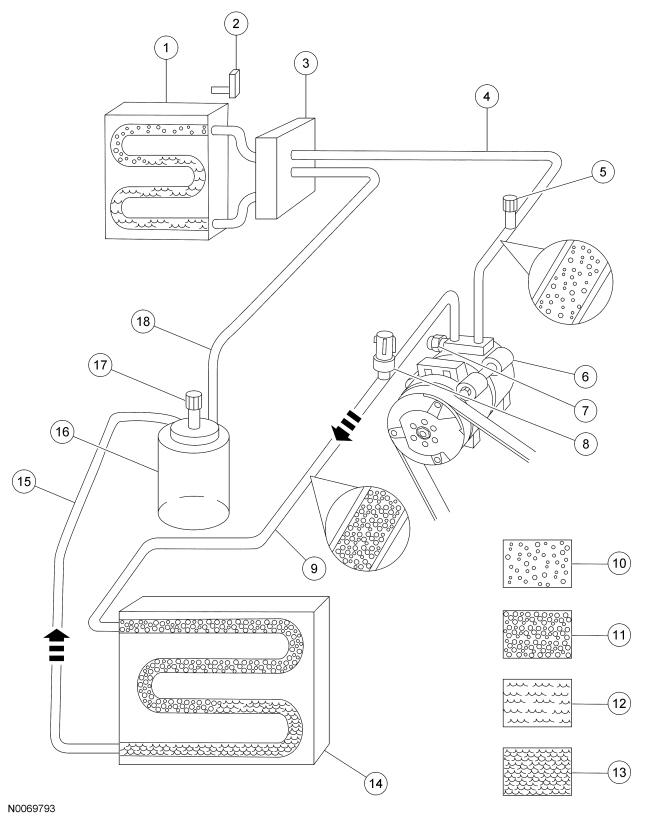
Thermostatic Expansion Valve (TXV) Type Refrigerant System - GTDI
| Item | Description |
|---|---|
| 1 | A/C evaporator core (part of 19850) |
| 2 | A/C evaporator core temperature sensor (part of 19850) |
| 3 | TXV |
| 4 | A/C suction line |
| 5 | A/C charge valve port (low side) |
| 6 | A/C compressor |
| 7 | A/C pressure relief valve |
| 8 | A/C pressure transducer |
| 9 | Compressor discharge line |
| 10 | Low-pressure vapor |
| 11 | High-pressure vapor |
| 12 | Low-pressure liquid |
| 13 | High-pressure liquid |
| 14 | A/C condenser core |
| 15 | Condenser-to-receiver-drier line |
| 16 | A/C receiver-drier |
| 17 | A/C charge valve port (high side) |
| 18 | Evaporator inlet line |
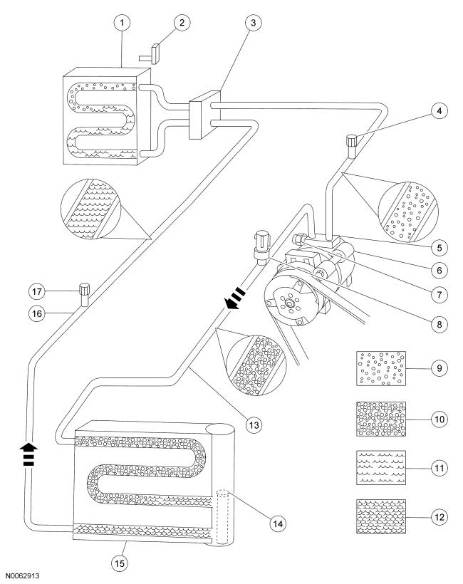
Thermostatic Expansion Valve (TXV) Type Refrigerant System - Ti-VCT
| Item | Description |
|---|---|
| 1 | A/C evaporator core (part of 19850) |
| 2 | A/C evaporator core temperature sensor (part of 19850) |
| 3 | TXV |
| 4 | A/C charge valve port (low side) |
| 5 | A/C suction line |
| 6 | A/C compressor |
| 7 | A/C pressure relief valve |
| 8 | A/C pressure transducer |
| 9 | Low-pressure vapor |
| 10 | High-pressure vapor |
| 11 | Low-pressure liquid |
| 12 | High-pressure liquid |
| 13 | Compressor discharge line |
| 14 | A/C desiccant bag |
| 15 | A/C condenser core with A/C receiver-drier |
| 16 | Condenser-to-evaporator line |
| 17 | A/C charge valve port (high side) |
Control System Logic
Climate Control System Network Communication
The controls for the climate control system are in 1 or more locations depending on vehicle option content:
- FCIM
- FDIM (part of APIM)
When the FDIM touchscreen or voice commands are used, the APIM sends a function request message over the I-CAN to the FCIM.
The FCIM receives the climate control selections from pressing the buttons on its own controls (interface), the APIM or IPC and sends the requests to the HVAC module in the following message path:
- The FCIM sends the requests over the I-CAN to the IPC.
- The IPC then relays the requests to BCM over the HS-CAN.
- Lastly, the BCM then sends the requests to the HVAC module over the MS-CAN.
The messaging path is followed in reverse for any status updates that need to be sent from the HVAC module to the FCIM, then, if applicable, to the IPC or FDIM (through the APIM).
When an airflow mode, fresh air or RECIRC mode, temperature setting or blower speed is selected, the FCIM sends this selection to the HVAC module using the message path described above.
When A/C is selected, the FCIM sends the selection to the HVAC module using the message path described above. If the ambient temperature is sufficient, the HVAC module then sends the request to the BCM over the MS-CAN. The BCM then sends the request to the PCM over the HS-CAN.
Controls and Compressor Cycling
The HVAC system uses inputs from the FCIM, FDIM and voice commands to provide the interface for the vehicle occupants to control the climate control system. When selections are made, the FCIM communicates the selections to the HVAC module which adjusts the climate control system components to achieve the desired state. When the climate control system is operating in AUTO mode, the required climate control system settings are determined by the HVAC module. The HVAC module then adjusts the climate control system components to the desired state.
The HVAC module utilizes an FET protective circuit strategy for its actuator outputs. Output load (current level) is monitored for excessive current (typically short circuits) and is shut down (turns off the voltage or ground provided by the module) when a fault event is detected. For additional information on HVAC module FET protection, refer to component description, Heating Ventilation Air Conditioning (HVAC) Module - HVAC in Component Description .
The PCM monitors the discharge pressure measured by the A/C pressure transducer. The PCM interrupts A/C compressor operation in the event the A/C pressure transducer indicates high system discharge pressures. It is also used to sense low charge conditions. If the pressure is below a predetermined value for a given ambient temperature, the PCM will not allow the A/C clutch to engage.
The evaporator temperature sensor is an input to the HVAC module. The HVAC module maintains evaporator core temperature and prevents icing of the evaporator core by switching the A/C request signal off before the evaporator temperatures are cold enough to freeze the condensation and by switching the A/C request signal on when the evaporator temperature rises above acceptable levels.
The HVAC module adjusts the air inlet door depending on the humidity measured by the in-vehicle temperature and humidity sensor. If the vehicle cabin becomes too humid and recirculated air is selected, the HVAC module adjusts the air inlet door to allow more fresh air. When the humidity level drops, it may adjust back to partial recirculated air. The HVAC module also adjusts the system based on in-vehicle temperature.
The sunload sensor supplies information to the HVAC module indicating the intensity of the sun on the vehicle and the HVAC module will make system adjustments based on the intensity.
When battery voltage is applied to the A/C compressor clutch field coil, the clutch disc and hub assembly is drawn toward the A/C clutch pulley. The magnetic force locks the clutch plate and hub assembly and the A/C clutch pulley together as one unit, causing the compressor shaft to rotate. When battery voltage is removed from the A/C compressor clutch field coil, springs in the clutch plate and hub assembly move the clutch plate away from the A/C clutch pulley.
For more information on compressor operation, refer to component description, Externally Controlled Variable Displacement Compressor (2.0L/3.5L GTDI) or Internally Controlled Variable Displacement Compressor (3.5L Ti-VCT) below.
Air Handling
Based on the climate control system settings the heater core and evaporator core housing directs airflow through the evaporator core and the heater core as needed, with the airflow exhausting through the appropriate outlets. Door actuators control the internal doors of the heater core and evaporator core housing to direct the airflow as selected by the climate control system settings. The air source is from outside air or recirculated passenger compartment air as determined by the air inlet mode door position.
The defrost/panel/floor mode door, temperature blend door and air inlet mode door actuators use a potentiometer to sense and communicate the door position to the HVAC module. When an airflow mode, desired driver or passenger temperature, or fresh air or recirculation mode is requested by the HVAC module the appropriate door actuator motor(s) is driven to the desired position, using the position sensed by the door actuator potentiometer to accurately position the door actuator.
The HVAC module will adjust the air inlet door depending on the humidity measured by the in-vehicle temperature and humidity sensor. If the vehicle cabin becomes too humid and recirculated air is not selected, the HVAC module will adjust the air inlet door to allow more recirculated air. When the humidity level drops, it will adjust back to fresh air. The HVAC module will also make system adjustments based on in-vehicle temperature.
The HVAC module uses the blower motor speed control to control the blower speed. For details on the Blower Motor Speed Control, refer to component description below.
AUTO
When AUTO is selected:
- the temperature control setting is manually set to the desired setting.
- the air inlet door is automatically controlled by the HVAC module based on the temperature setting.
- the mode door is automatically controlled by the HVAC module based on the temperature setting.
- the temperature blend doors are automatically controlled by the HVAC module, based on the temperature setting.
- the A/C compressor is automatically controlled by the HVAC module, based on the temperature setting. The A/C compressor will not operate if the outside temperature is below approximately 6°C (42.8°F).
- the blower motor is on. The blower motor speed is automatically controlled by the HVAC module based on the temperature setting, but can be manually overridden.
OFF
When OFF is selected:
- the air inlet door closes, preventing outside air and allowing only recirculated air.
- the blower motor is off.
MAX AC
When MAX A/C is selected:
- the air inlet door closes, preventing outside air and admits only recirculated air.
- the RECIRC indicator is illuminated (RECIRC forced on).
- the mode doors direct airflow to the instrument panel registers.
- the temperature blend doors move to the full cool position. Blended air temperature is available.
- the A/C request button is illuminated.
- the A/C compressor operates if the outside temperature is above approximately 6°C (42.8°F).
- the blower motor is commanded to the highest speed. The blower motor speed is adjustable.
PANEL
When PANEL is selected:
- the RECIRC request button is enabled. If the RECIRC request button is selected (indicator on), the air inlet door closes, preventing outside air from entering the passenger compartment. If the RECIRC request button is not selected (indicator off), the air inlet door opens, allowing only outside air into the passenger compartment.
- the mode doors direct airflow to the instrument panel registers.
- blended air temperature is available. Only when A/C compressor operation has been selected by pressing the A/C request button (indicator on) can the airflow temperature be cooled below the outside air temperature.
- the A/C request button is enabled. The A/C compressor operates and the indicator illuminates if the A/C request button is selected and the outside temperature is above approximately 6°C (42.8°F).
- the blower motor is on.
PANEL-FLOOR
When PANEL/FLOOR is selected:
- the RECIRC request button is enabled. If the RECIRC request button is selected (indicator on), the air inlet door closes, preventing outside air from entering the passenger compartment. If the RECIRC request button is not selected (indicator off), the air inlet door opens, allowing only outside air into the passenger compartment.
- the mode doors direct airflow to the floor duct and the instrument panel registers. A small amount of airflow from the side window demisters and defrost duct is present.
- blended air temperature is available. Only when A/C compressor operation has been selected by pressing the A/C request button (indicator on) can the airflow temperature be cooled below the outside air temperature.
- the A/C request button is enabled. The A/C compressor operates and the indicator illuminates if the A/C request button is selected and the outside temperature is above approximately 6°C (42.8°F).
- the blower motor is on.
FLOOR
When FLOOR is selected:
- the RECIRC request button is enabled. If the RECIRC request button is selected (indicator on), the air inlet door closes, preventing outside air from entering the passenger compartment. If the RECIRC request button is not selected (indicator off), the air inlet door opens, allowing only outside air into the passenger compartment.
- the mode doors direct airflow to the floor duct. A small amount of airflow from the defroster duct and side window demisters is present.
- blended air temperature is available. Only when A/C compressor operation has been selected by pressing the A/C request button (indicator on) can the airflow temperature be cooled below the outside air temperature.
- the A/C request button is enabled. The A/C compressor operates and the indicator illuminates if the A/C request button is selected and the outside temperature is above approximately 6°C (42.8°F).
- the blower motor is on.
FLOOR-DEFROST
When FLOOR/DEFROST is selected:
- the RECIRC request button is enabled. If the RECIRC request button is selected (indicator on), the air inlet door closes, preventing outside air from entering the passenger compartment. If the RECIRC request button is not selected (indicator off), the air inlet door opens, allowing only outside air into the passenger compartment.
- the mode doors direct airflow to the floor duct, the defroster duct and the side window demisters.
- blended air temperature is available.
- the A/C request button toggles the indicator on and off. To reduce fogging, the A/C compressor operates automatically, regardless of indicator status, if the outside temperature is above approximately 6°C (42.8°F).
- the blower motor is on.
DEFROST
When DEFROST is selected:
- the RECIRC request button is disabled. The air inlet door opens, allowing only outside air into the passenger compartment.
- the mode doors direct airflow to the defroster duct and side window demisters. A small amount of airflow from the floor duct is present.
- blended air temperature is available.
- the A/C request button toggles the indicator on and off. To reduce fogging, the A/C compressor operates automatically, regardless of indicator status, if the outside temperature is above approximately 6°C (42.8°F).
- the blower motor is on.
MyTemp
The MyTemp feature can be used to store and recall a preset driver's temperature. This feature is provided so this temperature can be quickly adjusted to a frequently used setting with a single button press. For additional information about MyTemp, refer to the Owner's Literature.
Remote Start - Message Center Set To Auto
This vehicle is equipped with a remote start feature. In addition to being able to start the vehicle remotely, the remote start feature also utilizes other vehicle systems to increase the level of comfort to the vehicle occupants upon entering the vehicle. For details on the remote start feature and the other vehicle systems it utilizes, REFER to Starting System , Remote Start (vehicles without Intelligent Access (IA)) or REFER to Starting System , Remote Start (vehicles with Intelligent Access (IA)).
When the remote start feature is used, the climate control system automatically sets certain parameters in an attempt to achieve a comfortable cabin temperature. These parameters are set based on outside air temperature. During remote start, the outside air temperature is continually evaluated and HVAC system behavior can change if the outside air changes between cold, moderate and warm temperatures.
For cold ambient air temperatures as determined by the HVAC module AUTO mode to request heat:
- the airflow mode is set to AUTO if Front Defrost is set to Off in the message center. (if the HVAC module requests FLOOR in AUTO mode, FLOOR/DEFROST will be used in remote start mode).
- the airflow mode is set to DEFROST if Front Defrost is set to Auto in the message center.
- the temperature is set to 22°C (71.6°F).
- the blower speed is set to AUTO.
- the air inlet mode is set to AUTO.
- A/C is set to AUTO.
For moderate and warm ambient air temperatures as determined by the HVAC module AUTO mode to request heat or cooling:
- the airflow mode is set to AUTO.
- the temperature is set to 22°C (71.6°F).
- the blower speed is set to AUTO.
- the air inlet mode is set to AUTO.
- A/C is set to AUTO.
Remote Start - Message Center Set To Last User Settings
This vehicle is equipped with a remote start feature. In addition to being able to start the vehicle remotely, the remote start feature also utilizes other vehicle systems to increase the level of comfort to the vehicle occupants upon entering the vehicle. For details on the remote start feature and the other vehicle systems it utilizes, REFER to Starting System , Remote Start (vehicles without Intelligent Access (IA)) or REFER to Starting System , Remote Start (vehicles with Intelligent Access (IA)).
When the remote start feature is used, the climate control system automatically sets certain parameters in an attempt to achieve a comfortable cabin temperature. These parameters are set based on outside air temperature. During remote start, the outside air temperature is continually evaluated and HVAC system behavior can change if the outside air changes between cold, moderate and warm temperatures.
For cold ambient air temperatures as determined by the HVAC module AUTO mode to request heat:
- the airflow mode is set to the last user setting if Front Defrost is set to Off in the message center.
- the airflow mode is set to DEFROST if Front Defrost is set to Auto in the message center.
- the temperature is set to the last user setting.
- the blower speed is set to the last user setting.
- the air inlet mode is set to the last user setting.
- A/C is set to the last user setting.
For moderate and warm ambient air temperatures as determined by the HVAC module AUTO mode to request heat or cooling:
- the airflow mode is set to the last user setting.
- the temperature is set to the last user setting.
- the blower speed is set to the last user setting.
- the air inlet mode is set to the last user setting.
- A/C is set to the last user setting.