Fuel Rail - 3.5L GTDI: Installation
- 1.NOTE: Make sure to thoroughly clean any residual fuel or foreign material from the cylinder head, block and the general surrounding area of the fuel rails and injectors.NOTE: Do not use compressed air to clean the tip of the fuel injector.NOTE: Do not use a brush to clean the tip of the fuel injector.
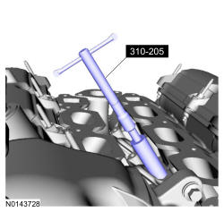
Using the Fuel Injector Brush, clean the fuel injector bore in the cylinder head. Special Tool(s): 310-205.
- 3.NOTE: Use care when removing the lower Teflon® seals, not to scratch, nick or gouge the fuel injector.NOTE: Do not attempt to cut the lower Teflon® seal without first pulling it away from the fuel injector or damage to the injector may occur.
- 1.
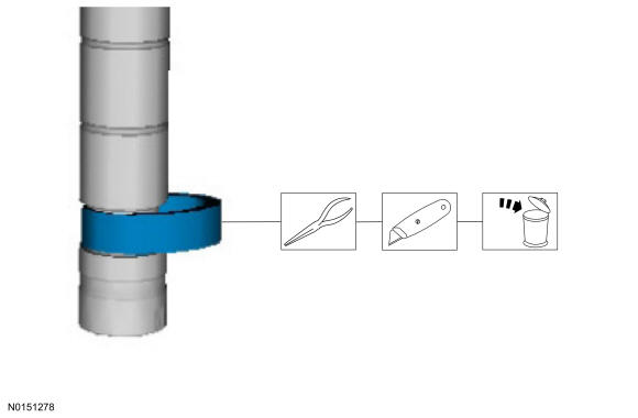
Pull the lower Teflon® seal away from the fuel injector.
- 2.
Carefully cut and discard the lower fuel injector Teflon® seal.
- 1.
- 4.
- 1.NOTE: Do not lubricate the new lower Teflon® fuel injector seals.
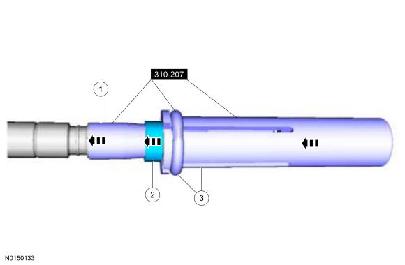
Install the Arbor on the fuel injector tip. Special Tool(s): 310-207.
- 2.NOTE: Once the Teflon® seal is installed on the Teflon® Seal Guide 310-207 (part of the Fuel Injector Seal Installer), it should immediately be installed onto the fuel injector to avoid excessive expansion of the Teflon® seal.NOTE: Make sure that new lower fuel injector Teflon® seals are installed.
Install the new Teflon® seal onto the Arbor, using the Pusher Tool (part of the Fuel Injector Seal Installer), slide the Teflon® seal along the Arbor. Special Tool(s): 310-207.
- 3.
Using the Pusher Tool, slide the Teflon® seal off of the Teflon® Seal Guide and into the groove on the fuel injector. Special Tool(s): 310-207.
- 1.
- 5.
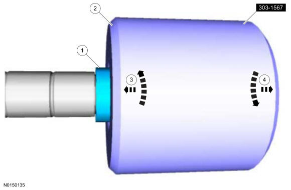
- 1.NOTE: Make sure the Teflon® seal is fully seated in the groove on the fuel injector before sizing the Teflon® seal.
Massage and warm the Teflon® seal with your fingers before the Teflon® seal sizer tool is installed. This will aid in installing the Teflon® seal sizer tool.
- 2.
Position the Teflon® seal sizer tool with the larger opening towards the Teflon® seal. Push while turning the Teflon® seal sizer tool 180 degrees. Special Tool(s): 303-1567.
- 3.
Once the Teflon® seal sizer tool is installed, check and make sure the Teflon® seal is in the sizing portion of the Teflon® seal sizer tool.
- 4.
After one minute, turn the Teflon® seal sizer tool back 180 degrees and remove.
- 1.
- 6.
-
NOTE: Use fuel injector O-ring seals that are made of special fuel-resistant material. The use of ordinary O-ring seals may cause the fuel system to leak. Do not reuse the O-ring seals.NOTE: Make sure that new upper fuel injector O-ring seals, upper fuel injector O-ring seal support rings and fuel injector retainer clips are installed.
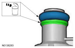
1. Install the new the fuel injector support rings.
- 2. Install the new fuel injector O-ring seals and lubricate them with clean engine oil. Material: Motorcraft® SAE 5W-30 Premium Synthetic Blend Motor Oil (US); Motorcraft® SAE 5W-30 Super Premium Motor Oil (Canada) XO-5W30-QSP (US); CXO-5W30-LSP12 (Canada); or equivalent.
- 3. Install the new the fuel injector clips.
-
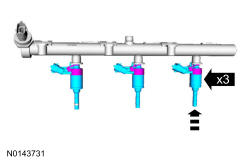
- 7.NOTE: LH shown in illustration, RH similar.NOTE: The anti-rotation finger of the fuel injector must slip into the groove of the fuel rail cup.
Install the fuel injectors to the fuel rail.
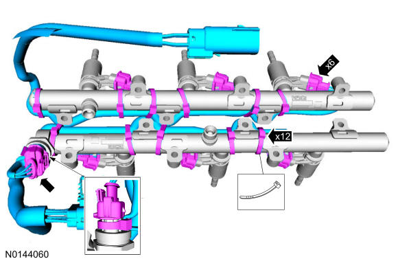
- 8.NOTE: It is very important to note the routing of the fuel charge wiring harnesses on the fuel rails and index-mark the location of the tie straps prior to removal or damage may occur to the wire harnesses during installation. The illustration details the correct fuel charge wire harness routing and tie strap positioning for installation.
Install the fuel charge wire harnesses, connect the Fuel Rail Pressure (FRP) sensor and the fuel injector electrical connectors. Install the tie straps to the index-marked locations on the fuel rails. Start by attaching the first tie strap farthest down the wire harness and continue to the connector end of the harness, leaving ample slack between the fuel injectors.
- 9.NOTE: It is very important to visually inspect the routing of the fuel charge wire harness to make sure that they will not be pinched or damaged between the fuel rail and the cylinder head during installation.NOTE: Do not lubricate the new lower Teflon® fuel injector seals.NOTE: Make sure that new fuel rail bolts are installed.NOTE: Tighten the bolts in a method that draws the fuel rail evenly to the head, preventing a rocking motion.
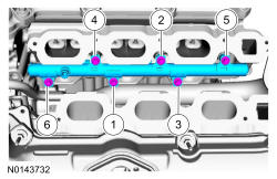
Install the fuel rail and the new fuel rail bolts. Tighten the fuel rail bolts in the following 3 stages.
- Stage 1: Push down on the fuel rail face above the injectors.
- Stage 1: Tighten to 10 Nm (89 lb-in) in the sequence shown in illustration.
- Stage 2: Tighten an additional 45 degrees in the sequence shown in illustration.
- 10.NOTE: It is very important to visually inspect the routing of the fuel charge wire harness to make sure that they will not be pinched or damaged between the fuel rail and the cylinder head during installation.NOTE: Do not lubricate the new lower Teflon® fuel injector seals.NOTE: Make sure that new fuel rail bolts are installed.NOTE: Tighten the bolts in a method that draws the fuel rail evenly to the head, preventing a rocking motion.
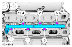
Install the fuel rail and the new fuel rail bolts. Tighten the fuel rail bolts in the following 3 stages.
- Stage 1: Push down on the fuel rail face above the injectors.
- Stage 1: Tighten to 10 Nm (89 lb-in) in the sequence shown in illustration.
- Stage 2: Tighten an additional 45 degrees in the sequence shown in illustration.
- 11.NOTE: Make sure that a new high pressure fuel tube and high pressure fuel tube bracket nut are installed.
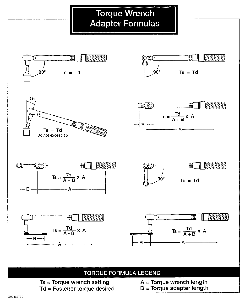
- 1.NOTE: Calculate the correct torque wrench setting for the following torque. Refer to the Torque Wrench Adapter Formulas in Fig 1
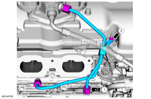
Install the high-pressure fuel tube and tighten the flare nuts in the following 3 stages.
- Stage 1: Tighten to 32 Nm (24 lb-ft).
- Stage 2: Wait 10 minutes to minimize pre-stress.
- Stage 3: Tighten to 32 Nm (24 lb-ft).
- 2.
- Tighten to 8 Nm (71 lb-in).
- 1.
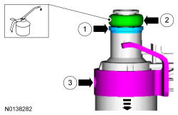
- 12.NOTE: When removing or installing the fuel injection pump noise insulator, spreading the openings will reduce the risk of damage.
Install the fuel injection pump noise insulator.
- 13.
Install the intake manifold, ENGINE - 3.5L GTDI .
- 14.
Connect the battery ground cable, REFER to Battery, Mounting and Cables .
- 15.
Pressurize the fuel system pressure, REFER to Fuel System - General Information .