Pinpoint Test I: Lost Communication To BCM (DTC %L(~U0140))
This test checks the function of the BCM to determine if it has an identifiable concern. This test should only be conducted after completing basic diagnostics, applicable Service Information Pinpoint Tests (PPTs) and then only if directed by the Service Information.
The BCM hardware test incorporates the following:
- A process using the PTS website and the IDS.
- The BCM on-demand self-test, other tests and steps that are used to validate the BCM functionality.
- Upon completion of the test, a repair recommendation is provided which will be either; "BCM replacement is Not recommended" or "BCM replacement is recommended".
- Once the test completes, a Repair Validation Code (RVC) is also generated. The RVC code is required for Ford paid repairs to claim the labor associated with completion of this test and if applicable, the labor and part for the replacement of the BCM.
The tools required to complete this test are:
- Rotunda IDS.
- VCM or VCM II.
- I1: INPUT REQUIRED INFORMATION
- Input the required information in the provided fields below.
* - Indicates Mandatory Field
Repair Order (RO) Date* [Enter value]
Repair Order (RO) Number* [Enter value]
Repair Order (RO) Line Number* [Enter value]
Dealership's P&A Code* [Enter value]
GO to I2.
- Input the required information in the provided fields below.
- I2: TEST ENTRY REQUIREMENTS NOTE: Low vehicle battery state-of-charge can affect the BCM operation and all network communications. Battery state-of-charge can be monitored on the scan tool. A red battery icon indicates low vehicle battery state-of-charge.NOTE: Certain vehicles are equipped with a Battery Management System (BMS) that shuts down select electrical features to preserve the battery charge. This may affect the operation of certain systems which may be noticed by the customer. If the Battery Management System (BMS) activates, it displays Low Battery Features Temporarily Turned Off in the message center. For additional information of the electrical energy management system, refer to Charging System .
- Carry out the following steps:
- connect a battery charger and set to the appropriate charge rate based on the battery SOC.
- apply the parking brake.
- if equipped with an automatic transmission, place the vehicle in Park (P), or if equipped with a manual transmission, place the vehicle in Neutral (N).
- connect the VCM I or II to the IDS desktop or laptop (do not start IDS).
GO to I3.
- Carry out the following steps:
- I3: CHECK THE NETWORK COMMUNICATION OPERATION NOTE: If the module does not communicate on the network, "Module not responding (or optional equipment module)" displays in the Description column.
- Ignition ON, engine OFF.
- Press the Read Vehicle Information button to view the results of the modules communicating on the network.NOTE: This step reads and then clears any continuous DTCs present.
- Retrieve the continuous memory DTCs.
- Do the modules that set DTC U0140 communicate on the network?
Yes No GO to I5. GO to I4.
- I4: DIAGNOSE THE NETWORK CONCERN
- Refer to Module Communications Network to diagnose the network concern. When the cause of the concern is identified, return to this step in the BCM hardware test.
- After the Service Information diagnostics/pinpoint tests were completed, do the results indicate the BCM as the cause of the concern?
Yes No GO to I8. GO to I9.
- I5: RECHECK FOR CONTINUOUS DTCS
- I6: CHECK FOR DTC U0140 SET IN MULTIPLE MODULES NOTE: If any bus off DTC is present, the fault is not currently present as the module had to communicate with the diagnostic scan tool to report the DTC.NOTE: Lost communication DTCs can falsely set during module programming operations. DTCs set immediately following the programming process and should be cleared to determine if they currently present.
- I7: VERIFY ALL WIRING CONNECTIONS
- Ignition OFF.
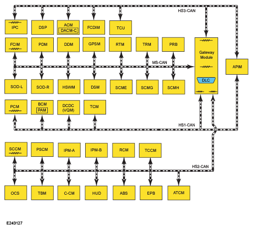
Most common layout/configuration shown, confirm this information in Module Communications Network by application.
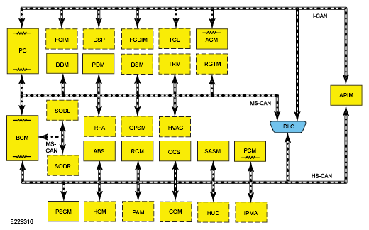
Focus, C-Max, Escape and Transit Connect layout/configuration
- Verify the integrity of all applicable network communication circuit splice and junction blocks. Refer to System Diagram in the appropriate Description and Operation (System Operation and Component Description) in Module Communications Network first before referencing wiring diagrams for connector information.
- Disconnect the module(s) setting the DTC U0140:xx.
- Disconnect all in-line electrical connectors between the module(s) that set DTC U0140:xx and the BCM.
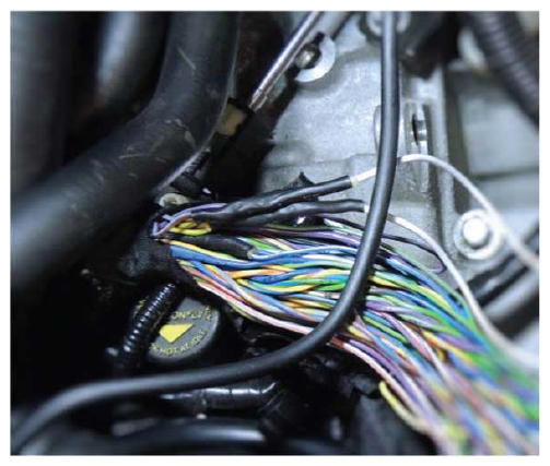
- Using a good light source, inspect and/or test all disconnected electrical connectors for the following:
- Corrosion - install new connector or terminal and clean the module pins
- Damaged or bent pins - install new terminals or pins
- Pushed-out pins - install new pins as necessary
- Spread terminals - install new terminals as necessary
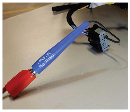
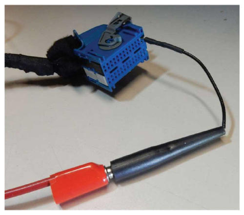
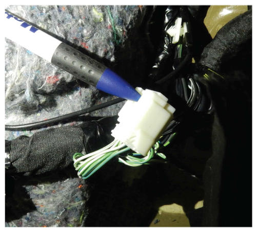
- Use of the appropriate flex probes is recommended to verify connector pin fit.
- REFER to GSB G0000041 Vehicles Joint Connector Information and Location fro additional on splice block repairs.
Recommended testing methods and reference wire harness splice components shown below.
- Are the connectors free of corrosion, damaged pins, bent pins, pushed-out pins and spread terminals?
Yes No GO to I8. REPAIR the connector or terminals as necessary.
Refer to OEM Connector Repair Procedures for schematic and connector information.
- I8: CHECK FOR CORRECT BCM OPERATION
- Ignition OFF.
- Disconnect and inspect all the BCM connectors.
- Repair:
- corrosion (install new connectors or terminals - clean module pins)
- damaged or bent pins - install new terminals pins
- pushed-out pins - install new pins as necessary
- Reconnect the BCM connectors and make sure they seat and latch correctly.
- Operate the system and determine if the concern is still present.
- Is the concern still present?
Yes No GO to I10. GO to I9.
- I9: THE BCM PASSED THE HARDWARE TEST- REPLACEMENT IS NOT RECOMMENDED NOTE: If the concern persists, please refer to the appropriate Service Information for further diagnostics. In some cases, with additional diagnosis or assistance from Ford resources, it may be determined that even though the BCM passed this Hardware Test, replacement is still necessary in an attempt to resolve a customer reported concern. In these cases, the BCM Hardware Test must still be fully completed, a test validation code generated and the code included on the Ford paid claim.
- Test results: The results of the test show that the BCM hardware test passed and that the BCM has no identifiable issues. Replacement of the BCM resolve the customer reported concern is therefore NOT recommended.
- For a Ford paid repair, obtain the BCM Hardware Repair Validation Code. This validation code is required to claim the BCM hardware test labor operation.
No fault found. If this is a Ford paid repair ensure that the BCM hardware test validation code is included on the claim form. When complete, select the "X" in the top right corner to close this procedure.
- I10: DESCRIBE THE FAILURE
- What was the customer identified symptom that led to this step?
-
* - Indicates Mandatory Field
Please provide the symptom that led to the BCM replacement.* [Enter value]
GO to I11.
- I11: THE BCM HARDWARE TEST FAILED - REPLACEMENT IS RECOMMENDED
- Test results: The results of the test show that the BCM failed.
- For a Ford paid repair, obtain the BCM Hardware Repair Validation Code. This validation code is required to claim the BCM (part), the BCM R&I labor and the BCM hardware test labor operations and must be included on the claim form.
INSTALL a new BCM.
Order a replacement BCM and include the validation code on the form.
If this is a Ford paid repair ensure that the BCM hardware test validation code is included on the claim form.
When complete, select the "X" in the top right corner to close this procedure.