Air Bag Warning Light Illuminated With Diagnostic Trouble Code (DTC) B141B And/Or B141C (16-0001)
WARNING: This page is about the Explorer Base, 2.0L Eng VIN 9, which is a different variant/trim than selected.
Publication date: 2016-01-04Reference number: 16-0001
Supersedes refnos: 15-0113
AIR BAG WARNING LIGHT ILLUMINATED WITH DIAGNOSTIC TROUBLE CODE (DTC) B141B AND/OR B141C
TECHNICAL SERVICE BULLETIN
Reference Number(s): 16-0001, Date of Issue:
January 4, 2016
Superceded Bulletin(s): 15-0113, Date of Issue:
July 23, 2015
| FORD: | 2014-2016 Explorer |
NOTE:
This article supersedes TSB 15-0113
to update the Service Procedure and Part List.
ISSUE
Some 2014-2016 Explorer vehicles equipped with second row inflatable seat belts may exhibit an air bag warning light illuminated with DTC B141B and/or B141C.
ACTION
Follow the Service Procedure steps to correct the condition.
SERVICE PROCEDURE
- Disconnect the battery. Refer to Workshop Manual (WSM), Section 414-01.
- Fold both of the second row seats forward to gain access to connectors C3133 and C3134.
- Remove the seat bottom covers from both sides. Refer to WSM, Section 501-10.
- On the left and right side, disconnect the connectors and remove the connector and wiring harness pushpin from its mounting on the seat frames.
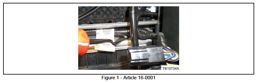
- On both sides, follow the seat harness and locate the next harness retaining pushpin and remove it from its mounting position to allow for more harness movement. Cut and discard the protruding end of the pushpin. (Figure 1)
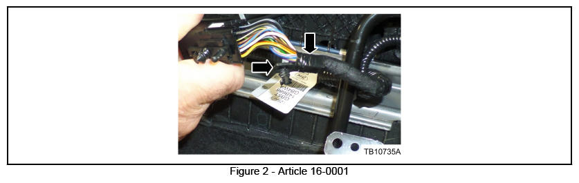
- On the male side of both connectors where the wiring harness is taped to the harness pushpin retainers, remove the retaining tape and the harness pushpin. Discard the pushpin. (Figure 2)
- Determine the vehicle's second row seat configuration.
- If the vehicle is equipped with the 60/40 seats proceed to Step 8.
- If the vehicle is equipped with second row armrest chairs proceed to Step 9.
- For vehicles with 60/40 seats, perform the following procedure:
- On the driver side cut the wires on the female side of C3133 and replace them with the new wiring pigtail. Only replace the length of wire removed from the harness. Solder the new wire to the existing circuits. Refer to Section 5 of the Wiring Diagram for the solder-splicing method.
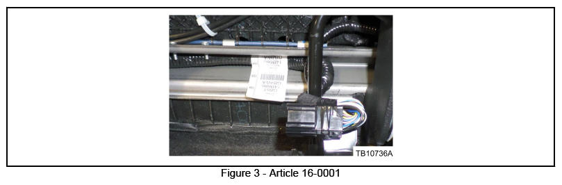
- On the male connector create a 15-20 mm (1/2-3/4") loop with the wiring harness and secure the harness to the connector using electrical tape. Make sure the wire loop does not contact the seat trim. Wrap the harness and connectors 3 times to provide harness stress relief and to prevent damage to the connector terminals when the seat is folded forward. (Figure 3)
- Reconnect the connector.
- Reattach the connector to the seat mounting with the existing pushpin.
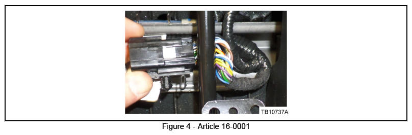
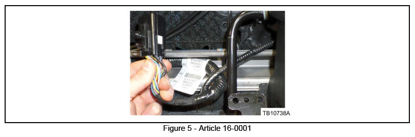
- On the passenger side, take the connector and route the seat harness to the other side of the black bar. (Figures 4 and 5)
- Cut the wires for the female connector C3134 and replace them with the new wiring pigtail. Make sure to replace only the length of wire removed from the harness. Solder the new wire to the existing circuits. Refer to Section 5 of the Wiring Diagram for the solder-splicing method.
- On the male connector create a 15-20 mm (1/2-3/4") loop with the wiring harness and secure the harness to the connector using electrical tape. Make sure the wire loop does not contact the seat trim. Wrap the harness and connectors 3 times around to provide harness stress relief and to prevent damage to the connector terminals when the seat is folded/tumbled forward. (Figure 3)
- Reconnect the connector.
- Reattach the connector to the seat mounting with the existing pushpin and proceed to Step 10.
- For vehicles with second row armrest chairs perform the following procedure:
- On both the passenger and driver side seat take the connectors and route the seat harness to the other side of the black vertical bar. (Figures 4 and 5)
- Cut the wires for both female connectors C3133 and C3134, and replace them with the new wiring pigtail. Only replace the length of wire removed from the harness. Solder the new wire to the existing circuits. Refer to Section 5 of the Wiring Diagram for the solder-splicing method.
- On the male connector side, create a 15-20 mm (1/2-3/4") loop with the wiring harness and secure the harness to the connector using electrical tape. Make sure the wire loop does not contact the seat trim. Wrap the harness and connectors 3 times to provide harness stress relief and to prevent damage to the connector terminals when the seat is folded forward. (Figure 3)
- Reconnect the connectors.
- Reattach both connectors to the seat mounting with the existing pushpins and proceed to Step 10.
- Reattach the seat bottom cover. Refer to WSM, Section 501-10.
- Reconnect the battery. Refer to WSM, Section 414-01
PARTS INFORMATION
OBTAIN LOCALLY
| Electrical Tape |
PARTS INFORMATION
| PART NUMBER | PART NAME |
|---|---|
| FU2Z-14S411-RA | Wiring Assembly (2 Req) |
WARRANTY INFORMATION
WARRANTY INFORMATION
| OPERATION | DESCRIPTION | TIME |
|---|---|---|
| 160001A | 2014-2016 Explorer: Perform Wiring Update Following The Service Procedure (Do Not Use With Any Other Labor Operations) | 2.8 Hrs. |
WARRANTY STATUS:
Eligible Under Provisions Of New Vehicle Limited Warranty Coverage.
Warranty/ESP coverage limits/policies/prior approvals are not altered by a TSB. Warranty/ESP coverage limits are determined by the identified causal part and verified using the OASIS part coverage tool.
DEALER CODING
| BASIC PART NO. | CONDITION CODE |
|---|---|
| 14A005 | 30 |