Road Force® Balancing Guide For Tire Vibrations And Accessing The Tire Warranty Conditions Guide (G0000168)
Reference number: G0000168
Supersedes refnos: 22-7105
ROAD FORCE® BALANCING GUIDE FOR TIRE VIBRATIONS AND ACCESSING THE TIRE WARRANTY CONDITIONS GUIDE
TECHNICAL SERVICE BULLETIN
| FORD: | All Models |
SUMMARY
This article supersedes G0000168 to update the vehicles affected and Service Information.
This bulletin will assist technicians with the Ford approved procedure for Road Force® balancing tire/wheel assemblies based on dealer equipment available.
For assistance with making warranty determinations on various tire failure modes, refer to the Tire Warranty Conditions Guide located under the Service Tips tab > Reference Guides on PTS.
SERVICE INFORMATION
Dealer Requirements For Equipment Based Diagnostics And Warranty Claim Submission Criteria For Road Force® Balancing
If the vehicle has been in service for over 200 mi (322 km), tire flat spotting from short-term parking should be eliminated by driving the vehicle 20 or more miles just prior to taking Road Force® measurements.
Use one of the following Ford approved Road Force® balancing procedures:
- Hunter 180 Matching
- Workshop Manual (WSM) Section 204-04A - General Procedures - Wheel to Tire Runout
Dealer Requirements For Equipment Based Diagnostics And Warranty Claims Submission Required Process Steps For Diagnostics And Submission Of A Tire Replacement Vibration Claim
Determine the equipment type used at your dealership or tire/wheel balancing (reference article below identifying equipment type).
Refer to appropriate equipment section in this GSB and follow instructions.
Refer to WSM Section 204-04A - Diagnosis and Testing - Wheels and Tires under the heading "Radial Runout Measurement - Loaded Hunter Road Force® Method" for vehicle-specific specifications.
Properly mark warranty return tires.
Use correct Service Labor Time Standards (SLTS) codes.
Document all diagnostic steps and dial indicator/Road Force® measurements in the technician comments of the warranty claim and on the shop copy of the repair order.
Wheel To Tire Runout Minimization Procedure
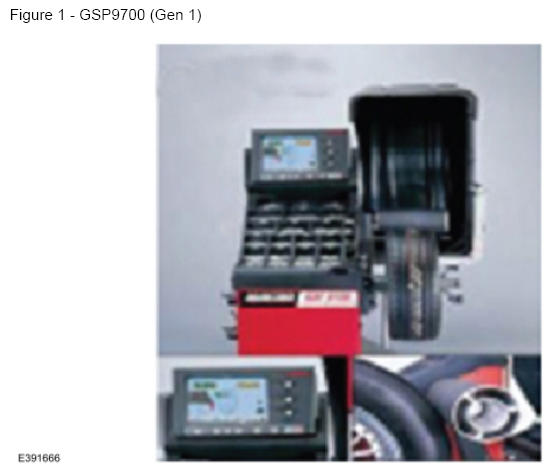
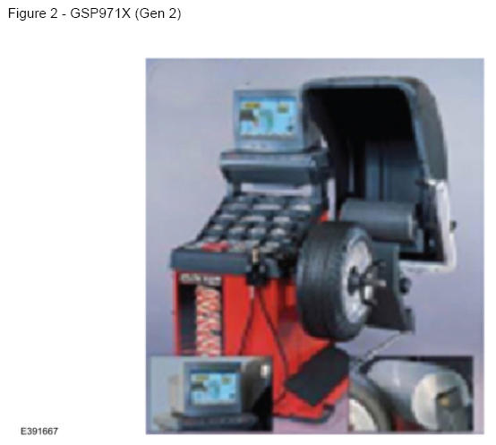
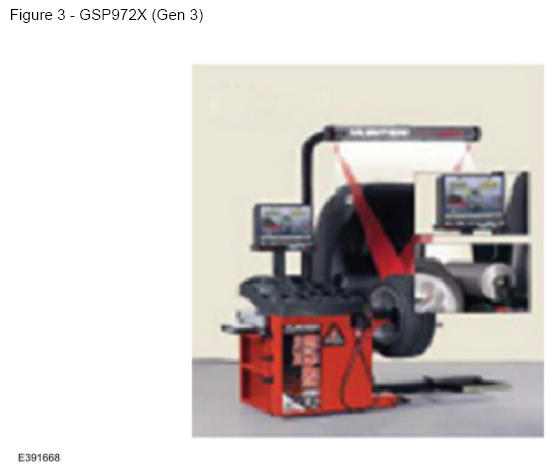
Hunter Equipment Model Identification
| Gen 1 | Gen 2 | Gen 3 | Gen 4 | Gen 5 | |
|---|---|---|---|---|---|
| Model Numbers | GSP9702 | GSP9712 | GSP9722 | RFT | RFE |
| Introduction Date | 9-Mar-1998 | 15-May-2001 | 12-Apr-2007 | 16-Mar-2012 | 27-Apr-2016 |
| Identifying Features | 6 in. roller | 9.5 in. roller | LCD monitor | Touch Screen | No dataset arms |
| Monitor Controls | 3 knobs | 1 knob | 1 knob | No knobs | No knobs |
| Monitor Type | Color CRT | Color CRT | Color LCD | Touch Screen | Touch Screen |
| Printer | Dot matrix | Dot matrix | Color inkjet | Color inkjet | Color inkjet |
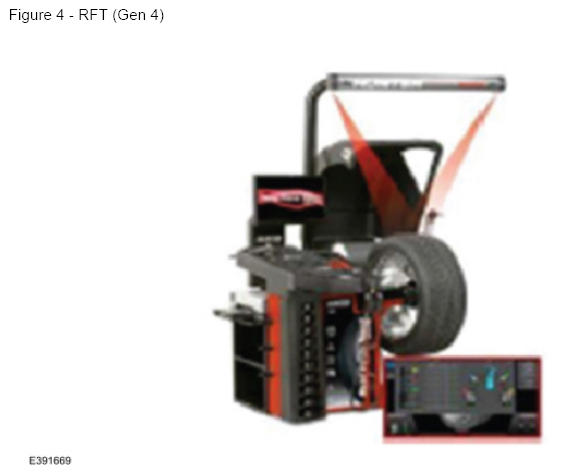
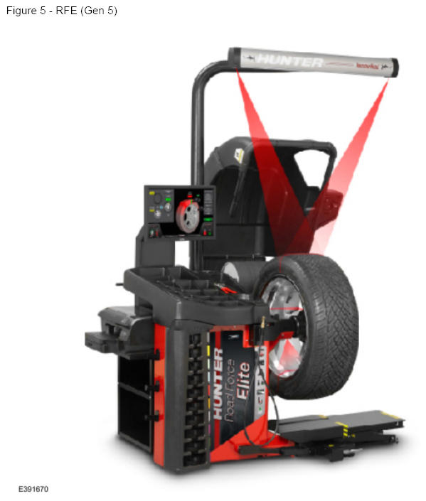
Equipment Type: Hunter Road Force® Touch/Road Force® Elite (Generation 4/Generation 5)
These balancer models include a procedure for 180 matching on the balancer display. This is the only Hunter procedure that matches Ford WSM Section 204-04A - General Procedures - Wheel to Tire Runout Minimization.
A second balancing procedure (it may be the default) likely exists on the equipment. Do not use that procedure. If the machine will not default to the 180 Matching Procedure, then it will need to be selected each time.
The 180 Matching Procedure can be launched by selecting the following buttons: Road Force® > Procedures > 180 Matching
Equipment Type: Hunter GSP9722 (Generation 3)
This model of balancer may include a procedure for Match Without Rim Runout on the balancer display. If this procedure is not included, then follow WSM section 204-04A - General Procedures - Wheel to Tire Runout Minimization.
Another balancing procedure likely exists on the equipment. Do not use that procedure, only the Hunter Match Without Rim Runout and WSM Wheel to Tire Runout Minimization procedure are approved for use on Ford tire/wheel assemblies.
The Match Without Rim Runout procedure should become the machine default setting after using it the first time. If it does not become the default, it will need to be selected each time.
The Match Without Rim Runout procedure can be launched by selecting the following: Show Runout And QuickMatching (1) > Runout/Matching (2) > Match Without Rim Runout (3)
Equipment Type: Hunter GSP9712 (Generation 1/Generation 2)
These balancer models do not include software that follows the WSM methodology.
The match mounting procedures in the software of these models should not be used. Instead, use only the Wheel to Tire Runout Minimization procedure found in WSM Section 204-04A - General Procedures.
Use these machines only to gather the necessary Road Force® measurements. Do not follow the prompts that appear for match-mounting.
Equipment Type: Other Brands/Models Of Balancer Equipment
Non-Hunter brand balancers will not include the Ford-approved procedure for match-mounting in their software.
Other balancing procedures that exist on non-Hunter brand equipment are not Ford approved and should not be used.
Equipment Type: Dial Indicator (Use Only When Road Force® Equipment Is Not Accessible)
Radial runout measurements can be taken using a dial indicator, if the preferred Road Force® balancing equipment is not available. (Figure 6)
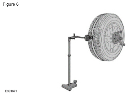
Refer to WSM section 204-04A - Diagnosis and Testing - Wheels and Tires under the heading Radial Runout Measurement - Dial Indicator Method for the approved process.
Loaded runout measurements are the preferred method for verifying tire serviceability. While a dial indicator can be used to optimize the position of the tire on the wheel, these unloaded runout measurements cannot accurately determine if the tire should be removed from service.
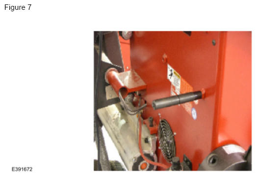
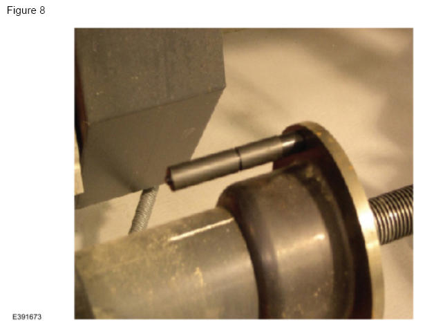
Equipment Settings and Calibration
It is important to run daily calibration checks on tire balancer equipment and re-calibrate when indicated. Most modern balancers utilize a calibration weight stored on the back of the machine. The weight is installed on the balancer's faceplate during calibration and a calibrate option is selected from the machine's menu. For specific instructions, reference the machine's user manual. (Figures 7-8)
Marking Tires Properly For Warranty Return
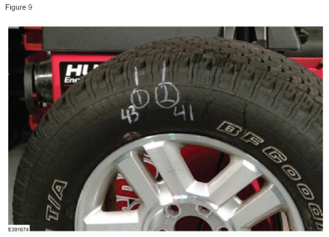
Any tire replaced under warranty must be marked with two Road Force® measurements and their locations as outlined in the Wheel to Tire Runout Minimization procedure in WSM Section 204-04A - General Procedures. Refer to Warranty And Policy Manual Section 3 for warranty requirements.
Each tire should be marked as indicated in the image where: (1) is the location of the initial measurement, and (2) is the location of the second measurement, taken after rotating the tire 180° on the wheel. The numbers 43 and 41 in the image are the Road Force® values in pounds for each of the two measurements. (Figure 9)
Acceptable Documentation for Tech Comments Section Of The Warranty Claim
Requirement: All road force or dial indicator measurements taken should be included in the warranty claim, as well as on the repair order hard copy. Per the Warranty And Policy Manual, it is the technician's responsibility to record key measurements/observations on the hard copy of the claim.
Examples Of Acceptable Tech Comments For Each Balancing Process Hunter 180 Matching Process
Hunter 180 Matching Process
- Drove vehicle 23 mi, verified vibration. Spec 25 lb, Initial Road Force 38,51,66,31. Re-index 180 - 14,39,40,27. Hunter Match Mount - NA,29,32,12. Replace 2 Tires.
Ford WSM-Road Force® Balancing Process
- Drove vehicle 20 mi, verified vibration. Spec 35 lb, Initial Road Force 46,12,18,58. Re-index tire 180 - 26, NA, NA,46. Re-index 90 per WSM Instruction - NA, NA, NA,41. Replaced 1 Tire.
Ford WSM-Dial Indicator Process (runout measurements in inches):
- Drove vehicle 21 mi, verified vibration. Spec 1.14 mm (0.045 in), Initial Measurements (in.) 0.107, 0.086,0.043,0.031. Re-index Tire 180-0.081,0.078, NA, NA. Re-index 90 per WSM Instructions - 0.085,0.041, NA, NA. Replaced 1 Tire.