Steering Gear: Installation
- Position the steering gear and install the new steering gear bolts.
- Tighten to 165 Nm (122 lb-ft).
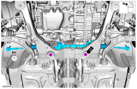
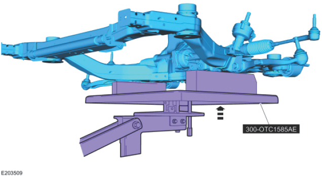
- Raise and align the subframe assembly to the witness marks made during removal.
- Use Special Service Tool: 300-OTC1585AE Powertrain Lift.
- Use the General Equipment: Wooden Block
- Install the new front subframe forward bolts.
- Tighten to 200 N.m (148 lb-ft)
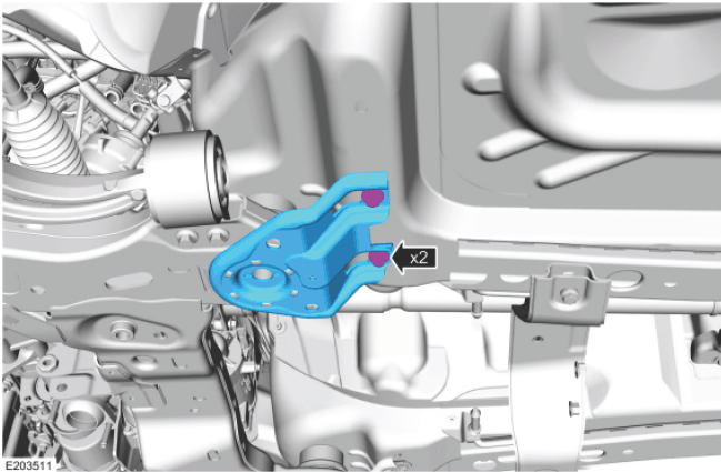
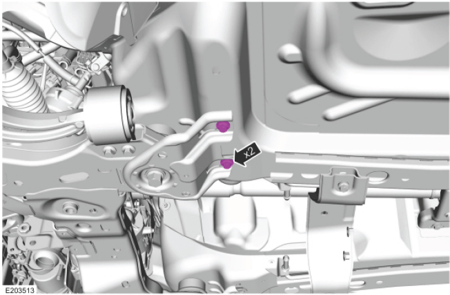
- Position the front subframe brackets and install the new front subframe bracket bolts.
- Install the new front subframe rearward bolts.
- Tighten to 200 N.m (148 lb-ft)
- Tighten the new front subframe bracket bolts.
- Tighten to 55 N.m (41 lb-ft).
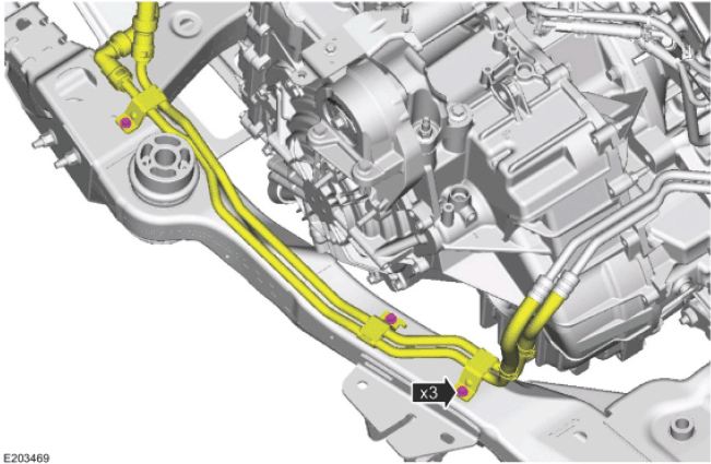
- Install the PTU cooler line mounting bracket bolts.
- Tighten to 11 N.m (97 lb-in).
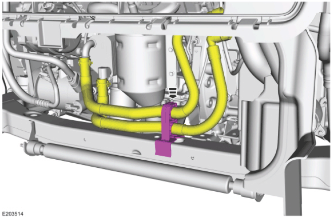
- Clip the oil cooler hose retainer to the front subframe.
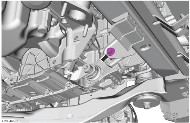
- Install the roll restrictor-to-subframe bolt.
- Tighten to 90 Nm (66 lb-in).
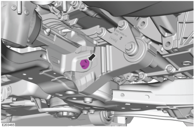
- Install the rear roll restrictor-to-subframe bolt.
- Tighten to 103 Nm (76 lb-in).
-
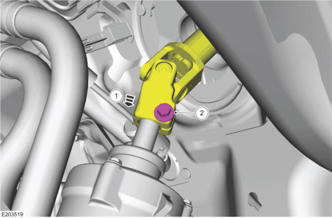
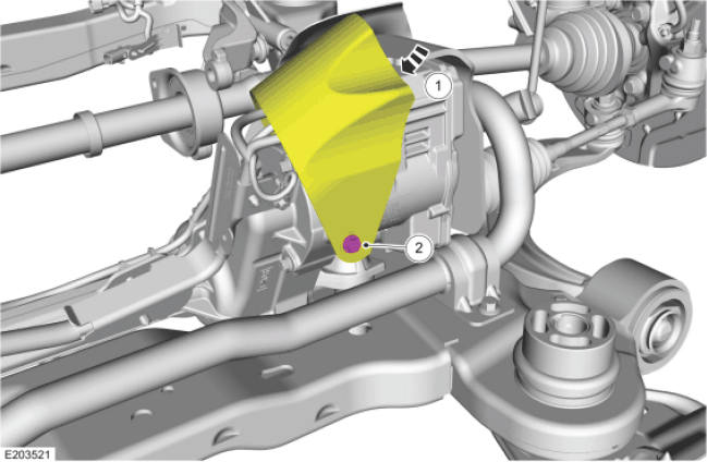
- Attach the steering column shaft coupler to the EPAS gear.
- Install the new steering column shaft bolt.
- Tighten to 25 N.m (18 lb-ft)
-
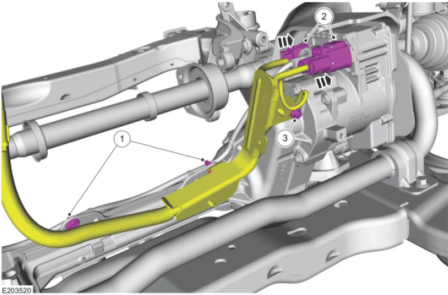
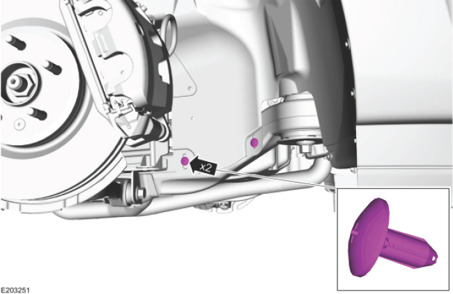
- Position the EPAS gear harness and attach the clips.
- Connect the EPAS gear harness electrical connectors.
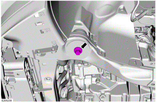
- Install the EPAS
gear harness ground bolt.
- Tighten to 7 N.m (62 lb-in).
-
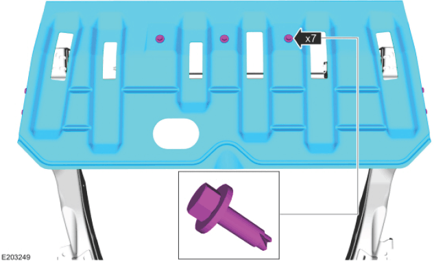
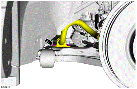
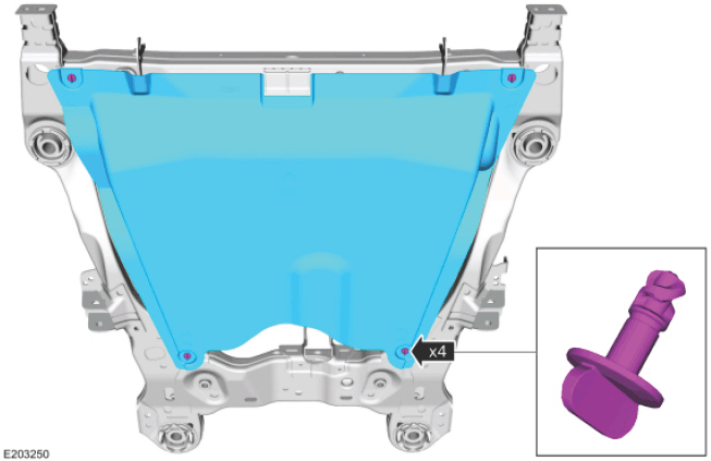
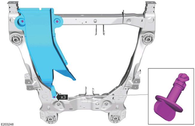
- Position the EPAS gear flap heat shield.
- Install the EPAS
gear flap heat shield bolt.
- Tighten to 11 N.m (97 lb-in).
- On both sides.
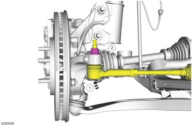
- Attach the tie rod end to the wheel knuckle.
- Install the new tie rod end nut.
- Tighten to 150 N.m (111 lb-ft).
- Position the stabilizer bar and install the new stabilizer bar bracket-to-front subframe bolts.
- Tighten to 55 N.m (41 lb-ft).
- Install the LH and RH exhaust flexible pipes. Refer to EXHAUST FLEXIBLE PIPE -- LH, 3.5L GTDI , or EXHAUST FLEXIBLE PIPE -- RH, 3.5L GTDI .
- Install the exhaust Y-pipe. Refer to EXHAUST Y-PIPE -- 3.5L TI-VCT .
- Install the exhaust Y-pipe. Refer to the appropriate Exhaust Service Information.
- Install the exhaust flexible pipe. Refer to EXHAUST FLEXIBLE PIPE -- 2.0L GTDI .
- Install the wheel arch liner to front subframe retainers.
- Install the underbody shield and the retainers.
- Install the underbody air duct and the retainers.
- Install the skid plate and the retainers.
- Install the front wheels and tires. REFER to INSTALLATION .
- When installing a new steering gear, it must be configured (using vehicle as-built data or module configuration information retrieved earlier in this procedure). Refer to the scan tool instructions to carry out PMI .
- Check and, if necessary, adjust the front toe. For additional information, refer to SUSPENSION SYSTEM -- GENERAL INFORMATION .
NOTE:
Install the steering gear from the RH side of the vehicle .
NOTE:
On both sides.
NOTE:
Only tighten the bolts finger tight at this stage.
NOTE:
On both sides.
NOTE:
On both sides .
NOTE:
On both sides .
NOTE:
If equipped .
NOTE:
If equipped .
NOTE:
If equipped .
NOTE:
Use the hex-holding feature to prevent turning of the stud while installing the tie rod end nut .
NOTE:
On both sides .
NOTE:
Vehicles equipped with 3.5L GTDI engine .
NOTE:
Vehicles equipped with 3.5L Ti-VCT engine .
NOTE:
Vehicles equipped with 3.7L Ti-VCT engine .
NOTE:
Vehicles equipped with 2.0L GTDI engine .
NOTE:
On both sides .
NOTE:
If equipped .
NOTE:
If equipped .
NOTE:
If equipped .