Pinpoint Test DL: Cylinder Head Temperature (CHT) Sensor: Introduction: Notes
This pinpoint test is intended to diagnose the following:
- cylinder head temperature (CHT) sensor (6G004)
- cylinder head temperature 2 (CHT2) sensor (6G004)
- harness circuits: CHT, CHT2, and SIGRTN
- PCM (12A650)
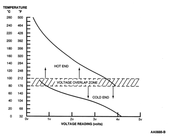
On applications that do not use an engine coolant temperature (ECT) sensor, the CHT sensor is used to determine the engine coolant temperature. To cover the entire temperature range of both the CHT and ECT sensors, the PCM has a dual switching resistor circuit on the CHT input. A graph showing the temperature switching from the COLD END line to the HOT END line, with increasing temperature and back with decreasing temperature is included. Note the temperature to voltage overlap zone. Within this zone it is possible to have either a COLD END or HOT END voltage at the same temperature. For example, at 90°C (194°F) the voltage could read either 0.60 volt or 3.71 volts. On applications with a CHT2 sensor, the PCM has a single resistor circuit on the CHT2 input. Refer to the table for the temperature to voltage expected values.
Voltage values calculated for VREF = 5 volts. These values can vary by 15% due to sensor and VREF variations.
| Temperature | CHT Sensor Values | |||
|---|---|---|---|---|
| °C | °F | Cold End (volts) | Hot End (volts) | Resistance (K ohms) |
| -40 | -40 | 4.89 | - | 965.808 |
| -30 | -22 | 4.81 | - | 513.019 |
| -20 | -4 | 4.67 | - | 283.664 |
| -10 | 14 | 4.45 | - | 162.584 |
| 0 | 32 | 4.14 | - | 96.255 |
| 10 | 50 | 3.73 | - | 59.175 |
| 20 | 68 | 3.26 | - | 37.387 |
| 30 | 86 | 2.74 | - | 24.215 |
| 40 | 104 | 2.23 | - | 16.043 |
| 50 | 122 | 1.76 | - | 10.85 |
| 60 | 140 | 1.36 | - | 7.487 |
| 70 | 158 | 1.04 | - | 5.268 |
| 80 | 176 | 0.79 | 3.99 | 3.775 |
| 85 | 185 | 0.69 | 3.86 | 3.215 |
| 90 | 194 | 0.60 | 3.71 | 2.75 |
| 95 | 203 | 0.53 | 3.56 | 2.361 |
| 100 | 212 | 0.46 | 3.41 | 2.034 |
| 110 | 230 | - | 3.07 | 1.523 |
| 120 | 248 | - | 2.74 | 1.155 |
| 130 | 266 | - | 2.41 | 0.8866 |
| 140 | 284 | - | 2.10 | 0.6891 |
| 150 | 302 | - | 1.81 | 0.5417 |
| 160 | 320 | - | 1.55 | 0.4301 |
| 170 | 338 | - | 1.33 | 0.3449 |
| 180 | 356 | - | 1.13 | 0.2791 |
| 190 | 374 | - | 0.96 | 0.2278 |
| 200 | 392 | - | 0.82 | 0.1875 |
| 210 | 410 | - | 0.70 | 0.155 |
| 220 | 428 | - | 0.60 | 0.130 |
| 230 | 446 | - | 0.51 | 0.109 |
| 240 | 464 | - | 0.44 | 0.092 |
| 250 | 482 | 0.35 | 0.078 | |
| 260 | 500 | 0.33 | 0.067 | |
| Temperature | CHT2 Sensor Values | ||
|---|---|---|---|
| °C | °F | Volts | Resistance (K ohms) |
| -40 | -40 | 4.995 | 965.808 |
| -30 | -22 | 4.990 | 512.947 |
| -20 | -4 | 4.969 | 283.651 |
| -10 | 14 | 4.949 | 162.585 |
| 0 | 32 | 4.917 | 96.248 |
| 10 | 50 | 4.870 | 59.173 |
| 20 | 68 | 4.839 | 37.387 |
| 30 | 86 | 4.802 | 24.216 |
| 40 | 104 | 4.707 | 16.043 |
| 50 | 122 | 4.578 | 10.851 |
| 60 | 140 | 4.411 | 7.487 |
| 70 | 158 | 4.202 | 5.269 |
| 80 | 176 | 3.953 | 3.775 |
| 90 | 194 | 3.667 | 2.750 |
| 100 | 212 | 3.354 | 2.038 |
| 110 | 230 | 3.018 | 1.523 |
| 120 | 248 | 2.680 | 1.155 |
| 130 | 266 | 2.350 | 0.8868 |
| 140 | 284 | 2.040 | 0.6893 |
| 150 | 302 | 1.757 | 0.5418 |
| 160 | 320 | 1.504 | 0.4301 |
| 170 | 338 | 1.282 | 0.3449 |
| 180 | 356 | 1.091 | 0.2791 |
| 190 | 374 | 0.928 | 0.2278 |
| 200 | 392 | 0.789 | 0.1875 |
| 210 | 410 | 0.672 | 0.1554 |
| 220 | 428 | 0.574 | 0.1297 |
| 230 | 446 | 0.491 | 0.1090 |
| 240 | 464 | 0.422 | 0.0921 |
| 250 | 482 | 0.363 | 0.0783 |
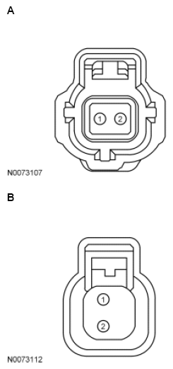
| Vehicle | Connector | Pin | Circuit |
|---|---|---|---|
| Transit Connect | A | 2 1 |
SIGRTN CHT |
| All other vehicles | B | 2 1 |
SIGRTN CHT |
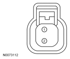
| Pin | Circuit |
|---|---|
| 2 | SIGRTN (Signal Return) |
| 1 | CHT2 (Cylinder Head Temperature 2) |