Mechanical Returnless Fuel System (MRFS)
NOTE:
The MRFS can be configured with a dual or variable speed fuel pump. The MRFS incorporates a fuel pump control module which is used to control the speed of the fuel pump. For additional information, refer to POWERTRAIN CONTROL HARDWARE in this service information.
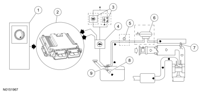
The MRFS uses a fuel tank with reservoir, the fuel pump, the fuel pump control module, the fuel pressure regulator, the fuel filter, the fuel supply line, the fuel rail, and fuel injectors.
For vehicles with gasoline direct fuel injection, a pressure accumulator is incorporated into the fuel line to prevent fuel vapor formation after several hours of cold soak and reduce crank time.
For additional information on the fuel system components, refer to ENGINE CONTROL COMPONENTS in this service information. Operation of the system is as follows:
- The fuel delivery system is enabled during ignition ON, engine OFF for 1 second and during crank or running mode once the PCM receives a CKP sensor signal. On vehicles with gasoline direct fuel injection, the high pressure fuel system may be under vacuum after several hours of cold soak. Fuel vapor may collect at the fuel injection pump, causing a long start condition. To prevent this, the fuel pump relay is energized for 1 or 2 seconds, depending on application, as soon as the dome light is commanded ON. This causes the fuel pump control module and the fuel pump to cycle for 1 or 2 seconds and purge any trapped air or fuel vapor from the high pressure fuel system.
- The fuel pump logic is defined in the fuel system control strategy and executed by the PCM.
- The fuel pump control module relay provides voltage to the fuel pump control module. Some vehicles use a replaceable relay inside the battery junction box; others use an internal relay in the body control module (BCM).
- The PCM commands a duty cycle to the fuel pump control module. The fuel pump control module reports diagnostic information to the PCM. The fuel pump control module controls the voltage to the FP based on the duty cycle request from the PCM. Voltage for the fuel pump is supplied by the fuel pump control module relay.
- For vehicles with gasoline direct fuel injection, a fuel pressure sensor monitors the low pressure fuel system.
- For vehicles with gasoline direct fuel injection, the fuel injection pump raises fuel system pressure to as high as 15 MPa (2175 psi), and delivers it to the fuel rail.
- The fuel injector is a solenoid-operated valve that meters the fuel flow to each combustion cylinder. The fuel injector is opened and closed a constant number of times per crankshaft revolution. The amount of fuel is controlled by the length of time the fuel injector is held open. The fuel injector is normally closed and is operated by the PCM.
- There are 3 to 5 filtering or screening devices in the fuel delivery system. For additional information, refer to FUEL SYSTEMS , in this service information.
- The FP assembly contains the fuel pump, the fuel pressure regulator, lifetime fuel filter and the fuel sender assembly. The fuel pressure regulator is attached to the FP assembly and regulates the pressure of the fuel supplied to the fuel injectors. The fuel pressure regulator controls the pressure of the clean fuel as the fuel returns from the fuel filter. The fuel pressure regulator is a diaphragm-operated relief valve. Fuel pressure is established by a spring preload applied to the diaphragm. The FP assembly is located in the fuel tank.