EMD Systems
EMD was required on all 2007 model year and beyond California gasoline and diesel fueled on road heavy duty engines used in vehicles over 14, 000 lbs GVWR. EMD systems are required to functionally monitor the fuel delivery system, exhaust gas recirculation (EGR) system, particulate matter trap, as well as emission related PCM inputs for circuit continuity and rationality, and emission related outputs for circuit continuity and functionality. For gasoline engines which have no particulate matter trap, EMD requirements are very similar to current OBD I system requirements. As such, OBD I system philosophy is employed, the only change being the addition of some comprehensive component monitor (CCM) rationality and functionality checks.
The EMD vehicles use the same PCM, CAN, serial data communication link, J1962 DLC, and PCM software as the corresponding OBD II vehicle. The only difference is the possible removal of the rear oxygen sensors, FTP sensor, EVAP canister vent valve, and a different PCM calibration.
Starting in the 2010 model year, EMD requires functional monitoring of the NO X aftertreatment system on gasoline engines. This requirement is commonly known as EMD+.
The following list indicates what monitors and functions have been altered from OBD II for gasoline engine EMD calibrations:
| Monitor/Feature | Calibration for Gasoline Engines |
|---|---|
| Catalyst Monitor | Functional catalyst monitor required starting in the 2010 model year. |
| Misfire Monitor | Calibrated in for repair, all DTCs are non-MIL. Catalyst damage misfire criteria calibrated out, emission threshold criteria set to 4%, enabled between 66°C (150°F) and 104°C (220°F), 254 second startup delay. |
| Oxygen Sensor Monitor | Front O2 sensor lack of switching tests and all circuit and heater tests calibrated in, response or delay test calibrated out. Rear O2 sensor functional tests and all circuit and heater tests calibrated in, response or delay test calibrated out. |
| EGR or VCT Monitor | Same as OBD II calibration except that DTC P0402 test uses a higher threshold. |
| Fuel System Monitor | Fuel system monitor and fore aft oxygen sensor (FAOS) monitor same as OBD II calibration, Air Fuel Ratio Imbalance monitor calibrated out. |
| Evaporative Emission (EVAP) System Monitor | EVAP system leak check calibrated out, fuel level input circuit checks retained as non-MIL. Fuel tank pressure sensor and EVAP canister vent valve may be deleted. |
| PCV Monitor | Same hardware and function as OBD II. |
| Thermostat Monitor | Thermostat monitor calibrated out. |
| Comprehensive Component Monitor (CCM) | All circuit checks, rationality and functional tests are the same as OBD II. |
| Communication Protocol and DLC | Same as OBD II, all generic and enhanced scan tool modes work the same as OBD II, but reflect the EMD calibration that contains fewer supported monitors. OBD supported PID indicates EMD. |
| MIL Control | Same as OBD II, it takes 2 drive cycles to illuminate the MIL. |
The following monitor descriptions provide a general description of each OBD monitor. In these descriptions the monitor strategy, hardware, testing requirements, and methods are presented to provide an overall understanding of monitor operation. An illustration of each monitor may also be provided. These illustrations should be used as typical examples and are not intended to represent all possible vehicle configurations.
Each illustration depicts the PCM as the main focus with primary inputs and outputs for each monitor. The icons to the left of the PCM represent the inputs used by each of the monitor strategies to enable or activate the monitor. The components and subsystems to the right of the PCM represent the hardware and signals used while carrying out the tests and the systems being tested. The CCM illustration has numerous components and signals involved which are illustrate generically. When referring to the illustrations, match the numbers to the corresponding numbers in the monitor descriptions for a better understanding of the monitor and associated DTCs.
These icons are used in the illustrations of the OBD monitors and throughout this service information.
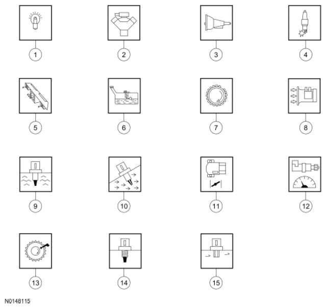
| Item | Number | Description |
|---|---|---|
| 1 | - | Malfunction Indicator Lamp (MIL) |
| 2 | - | Base Engine Components |
| 3 | - | Transmission |
| 4 | - | Ignition System |
| 5 | - | A/C Or Heater System |
| 6 | - | Fuel Level Input (FLI) |
| 7 | - | RPM |
| 8 | - | Mass Airflow (MAF) |
| 9 | - | Engine Coolant Temperature (ECT) |
| 10 | - | Intake Air Temperature (IAT) |
| 11 | - | Throttle Position (TP) |
| 12 | - | Vehicle Speed |
| 13 | - | Camshaft Position (CMP) |
| 14 | - | Cylinder Head Temperature (CHT) |
| 15 | - | Manifold Absolute Pressure (MAP) |