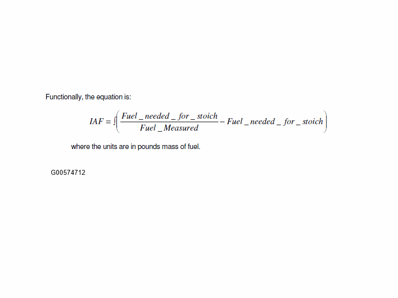
Integrated Air/Fuel Method
The Integrated Air/Fuel Catalyst Monitor assesses the oxygen storage capacity of a catalyst after a fuel cut event. The monitor integrates how much excess fuel is needed to drive the monitored catalyst to a rich condition starting from an oxygen-saturated, lean condition. Therefore, the monitor is a measure of how much fuel is required to force catalyst breakthrough from lean to rich. To accomplish this, the monitor runs during fuel reactivation following a Decel Fuel Shut Off (DFSO) event. The monitor completes after a calibrated number of DFSO monitoring events have occurred. The IAF catalyst monitor can be used with either a wide range O2 sensor (UEGO) or a conventional switching sensor (HEGO).
The monitor runs during reactivation fueling following an injector cut. The diagram below shows examples of one DFSO event with a threshold catalyst and with a Full Useful Life catalyst where:
- INJON = # of injectors on.
- CMS is the catalyst monitor sensor voltage. When the rear O2 sensor crosses 0.45 volts (i.e. rich) the monitor will complete for the given DFSO event.
- LAM (LAMBDA) is the front O2 sensor (UEGO) signal.
- CATMN_IAF_SUM is the integral from the equations above (Y axis on the right).
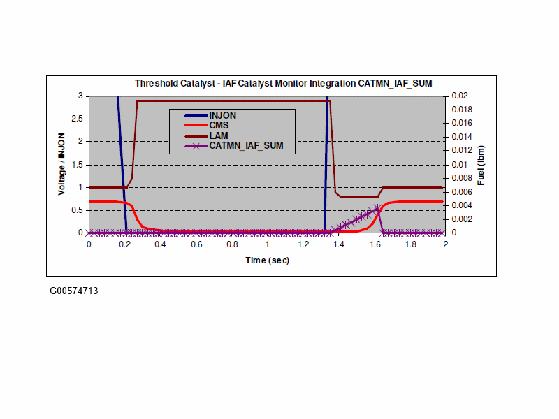
In this example, CATMN_IAF_SUM is small because it doesn't take much fuel to break though a low oxygen storage threshold catalyst.
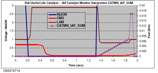
In this example, CATMN_IAF_SUM is much larger because it takes a substantial amount of fuel to break through a high oxygen storage threshold catalyst.
Reactivation fuel is limited by the catalyst monitor to optimize fuel economy and minimize emissions. A "green" catalyst with a lot of oxygen storage capability would require a large amount of reactivation fuel to completely break through and get the rear O2 sensor to switch rich. Reactivation fuel is clipped to a maximum level so that normal closed loop fuel control can be resumed when a calibrated amount of reactivation fuel has been delivered.
There are two sets of entry conditions into the IAF catalyst monitor. The high level entry conditions determine that the monitor would like to run following the next injector fuel cut event. The lower level entry conditions determine that the fuel cut-off event was suitable for monitoring and the monitor will run as soon as the injectors come back on.
- The high level entry conditions are met when:
- There are no senor/hardware faults
- The base monitor entry conditions have been met (ECT, IAT, cat temp, fuel level, air mass)
- Required number of DFSO monitoring event have not yet completed
- The lower level entry conditions are met when:
- The injectors are off
- The catalyst is believed to be saturated with oxygen (rear O2 indicates lean)
- The catalyst/rear O2 has been rich at least once since the last monitor event.
The "Gap"
The catalyst monitor uses response of the rear O2 sensor (internally called a CMS, Catalyst Monitor Sensor) to assess the oxygen storage capacity of the catalyst. If the rear O2 sensor slows down, it will look as though the catalyst has more oxygen storage than it actually has. If the delay gets large enough, the catalyst monitor could falsely pass a deteriorated catalyst. In practice, the rear O2 sensor response rate is monitored by Rear HO2S Decel Fuel Shut Off Response Test. A slow rear O2 sensor will set a DTC P013A/P013C or P013E/P014A DTC and illuminate the MIL. The region where a slow rear O2 sensor affects the catalyst monitor results up to the point where the Rear HO2S Decel Fuel Shut Off Response Test will flag a slow sensor is commonly refer to as a "gap". The OBD regulations require that manufacturers minimize any gap remaining between the worst performing acceptable rear O2 sensor and a sufficient sensor. In other words, the "gap" is the difference between the sensor delay that the Rear O2 sensor monitor can detect versus the sensor delay that will false pass the catalyst monitor.
On one end, the gap can be reduced by making the Rear HO2S Decel Fuel Shut Off Response Test more accurate. This can be accomplished by reducing the variability in the slew rate calculation by sampling the rear O2 signal faster and employing improved filtering and averaging techniques. The resulting slew rate is a direct measurement of sensor response. The slew rate calculation has more variability for a fast sensor versus a slow sensor. This is because you get a lot of sensor voltage samples on a slow sensor, but you only get a few on a fast sensor. This characteristic, however, provides us with an accurate slew rate for a slow sensor - the sensor of interest.
On the other end, the gap can be reduced by calibrating the catalyst monitor thresholds with a worst case, slow sensor. Although this reduces the gap, it increases the potential to falsely fail an acceptable catalyst, and it increases the amount of reactivation fuel needed to complete the catalyst monitor. This increases fuel consumption and emissions.
The example below the Full Useful Life catalyst monitor distribution shifts to the right towards the threshold catalyst distribution. This reduces the separation between acceptable and failed catalyst and increases the amount of reactivation fuel needed to complete the monitor.
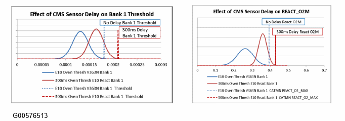
Instead of calibrating to the worst case (slow) sensor, strategy was added to adjust the catalyst monitor thresholds to account for the sensor delay. The "No-delay" CMS slew rate/slope measurement has a lot of variability however; a slow sensor has very tight slew rate/slope distribution. This characteristic was used to accurately adjust cat monitor thresholds for slow sensor, where it is the most critical.
- The delay calibration value will be set to the fault limit of the Rear HO2S Decel Fuel Shut Off Response Test. In this example, the monitor detects and sets a MIL for a 500 msec fault level.
- The no delay calibration will be set to the CMS delay that begins to have an observable effect on catalyst monitor results. In the example above this point occurs at a 300 msec delay.
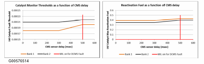
- Between 300 msec and 500 msec delay, the fault threshold will be a linear interpolation between the 300 msec and 500 msec thresholds.
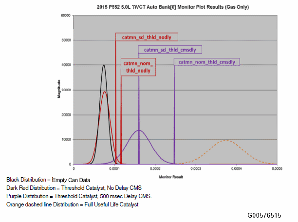
Catalyst monitor thresholds are a function CMS slew rate/slope as shown in the chart below. In the example shown below, the following relationships were used to determine the calibration:
Similarly, the reactivation fuel limits are a function CMS slew rate/slope as shown in the chart below.
The variable thresholds apply to the normal EWMA as well as the Fast Initial Response and the Step Change Logic thresholds.
- catmn_scl_thld_nodly => Set to the max of (Threshold No Delay mean or Empty Can mean + 3 sigma). The chart shows the scl_thld_nodly = Empty can mean + 3 sigma.
- catmn_scl_thld_cmsdly => Set to: max of (Threshold 500 msec Delay mean or Empty Can mean + 3 sigma). The chart shows the scl_thld_ cmsdly = 500 msec mean
- catmn_nom_thld_nodly => Set to the max of (Threshold No Delay mean + 3 sigma, or empty can + 3 sigma)
- catmn_nom_thld_cmsdly => Set to the max of (Threshold 500 ms mean + 3 sigma or empty can + 3 sigma)
Step Change Logic thresholds:
Normal EWMA and Fast Initial Response thresholds: